This thread has been locked.

If you have a related question, please click the "Ask a related question" button in the top right corner. The newly created question will be automatically linked to this question.

DS250DF230: Mclaren - Need help to understand the connection topology for accessing retimer using SIGCON GUI with USB2ANY device

Part Number: DS250DF230
Other Parts Discussed in Thread: USB2ANY, , DS250DF210,

Tool/software:

Hi,

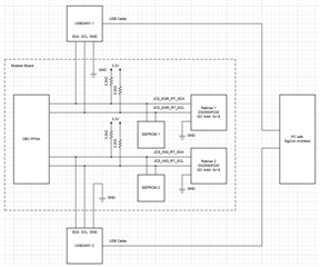
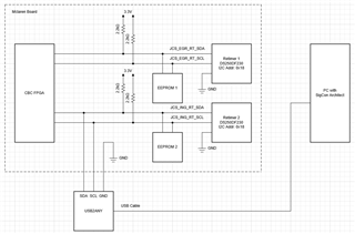
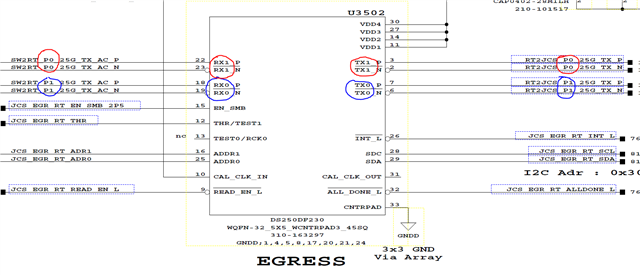
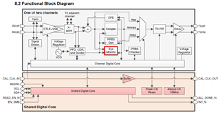
The following snapshot represents the block diagram of the section where TI retimer is used in Mclaren board.

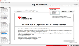
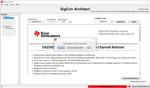
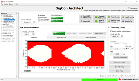
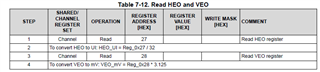
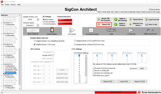
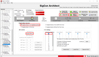
We're planning to use SIGCON GUI (with DS250DF230 updater file) to read/write TX settings, start/stop PRBS, PRBS BER, dump dfe Rx settings, read internal Eye (HEO,VEO) etc. Need help to understand the connection points for USB2ANY device in the Mclaren board.

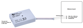
For your reference, adding below the block diagram showing SDA/SCL connections to the two TI retimer devices DS250DF230 in Mclaren board.

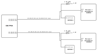
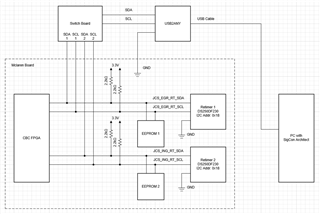
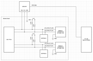
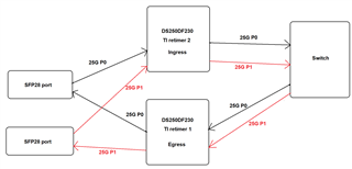
I got an idea from our my colleague who used SIGCON tool before for another project, and I have created one diagram (see below). But if this is correct, I want to know how can we probe the wires at TI retimer SDA/SCL/GND pins in Mclaren board. Because those pins are already connected to other two devices as shown in the above snapshot. It would be helpful if you can update the above block diagram with the changes required for connecting TI retimer to USB2ANY device.

Please let me know if you need any further information.

Regards

Vimal Vivek

  • Hi Vimal,

    Request noted. My team will get back to you ASAP with our feedback and suggestions.

    Regards,

    Rodrigo Natal

    HSSC Applications Manager

  • Hi Vimal,

    I have a few questions about your system before I propose USB2ANY connections.

    1. What is the I2C address of each retimer?
    2. Is it required for each retimer to read its configuration from the EEPROM? Would it be an issue to disconnect each EEPROM?
    3. Would it be an issue to connect I2C buses JCS_EGR_RT and JCS_ING_RT together?

    Best,

    Lucas

  • Hi Lucas,

    Here's the response for your questions from our HW engineer.

    1) 0x18 for both
    2) Software want the parts to initialize themselves to 25G when the card is powered up
    3) Cannot connect the two since they are both at the same I2C adr.

    Regards

    Vimal Vivek

  • Hi Vimal,

    Thank you for answering my questions. I have come up with 2 different options to access both retimers with SigCon Architect.

    Option 1: Using 2 USB2ANYs

    Within SigCon Architect GUI, you can select which USB2ANY to interface with. To tell the difference between USB2ANY 0 and 1, you can use the "Toggle LED" button and inspect which USB2ANY LED is flashing.

    Option 2: Using 1 USB2ANY with a switch

    A switch can be used to determine which I2C network is connected to the USB2ANY. There is a lot of flexibility in how the switch could be implemented. One idea is to solder headers onto a perf board and utilize jumpers to switch between each retimer.

    Do you have access to the DS250DF230 MySecure resources folder? You will need to download the DS250DF210 SigCon Architect profile updater to use SCA with your retimers.

    If you are having trouble establishing a connection with SigCon Architect, here are some debug steps to watch out for.

    • Make sure your FPGA or another device isn't controlling or holding the I2C lines.
    • Make sure both retimers successfully finished reading their configurations from the EEPROMs. This is indicated by the ALL_DONE_N pin output going low.

    Best,

    Lucas

  • Hi Lucas,

    Thanks, your detailed response.

    I think we've only one USB2ANY device with us. Will confirm that with our team. Just in case if that's the scenario, I think I can also go with connecting one I2C lane first, take the measurements. then connect next I2C lane and so on - right? I understand that using a switch as you mentioned in Option 2 is better, where once the setup is done, we don't even need to touch on it (except changing jumper to each ports) till the whole measurements are done. Apart from this, are there any differences between following Option 2 v/s doing the measurement by connecting one lane at a time without a switch? If the later one is fine, can you share the block diagram showing how that connection should be in Mclaren board?

    I received updater file for DS250DF230 from TI sometime back. I guess that updater file will be same for one device, and won't undergo any upgradations - is my understanding correct? Else if there is any latest version, could you please share the link to download that?

    Regards

    Vimal Vivek

  • Hi Vimal,

    I shared options 1 and 2 under the assumption that you would not be able to make modifications on the board to access each retimer. There should be no issues with connecting the USB2ANY to one I2C bus at a time to access each retimer.

    Here is a block diagram showing USB2ANY connection to retimer 1.

    And here is USB2ANY connection to retimer 2.

    I received updater file for DS250DF230 from TI sometime back. I guess that updater file will be same for one device, and won't undergo any upgradations - is my understanding correct? Else if there is any latest version, could you please share the link to download that?

    That's correct, the DS250DF230 updater file has not undergone any revisions, and there is no plan to make future revisions.

    Best,

    Lucas

  • Hi Lucas,

    Can you share DS250DF230 updater file once?

    Regards

    Vimal Vivek

  • Hi Lucas,

    After connecting as per the block diagram you suggested, I'm seeing this in SIGCON GUI. Seems like I've wrong updater file.

    Regards

    Vimal Vivek

  • Hi Vimal,

    SigCon Architect is looking for an 8-bit I2C address. Please change your address to 0x30.

    Best,

    Lucas

  • Hi Lucas,

    I've added the updater file for DS250DF210 instead of DS250DF230, and so I'm seeing DS250DF210 in Sigcon architect GUI. So here, do you meant to say that I don't need to load any new updater file for DS250DF230? May I know why is that?

    And the i2c address for the retimer is 0x18. How is it related to 0x30? Could you please help understand that?

    Regards

    Vimal Vivek

  • Hi Vimal,

    The DS250DF210 profile is the one intended for use with DS250DF230, sorry this is a bit unintuitive. The profile you are using is correct.

    I2C addresses can be given as 7-bit or 8-bit. This is because the address contains 7 unique bits + 1 read/write bit. For our Ethernet retimers and redrivers, we reference and use the 8-bit address. A 7-bit address of 0x18 is equivalent to an 8-bit address of 0x30.

    Best,

    Lucas

  • Hi Lucas,

    Ok, thanks for the clarification.

    I'll check by changing i2c address to 0x30.

    Meanwhile could you please let me know if any other changes or any settings need to be done? Are there anything else which I need to take care of for getting SIGCON tool work properly?

    As I understand, with respect to the retimer in Mclaren board, only i2c address is needed for accessing through SIGCON GUI - is my understanding correct?

    And, we need to generate PRBS pattern, read PRBS error, adjust TX equalization taps, adjust RX equalization taps etc. Hope all these are possible in SIGCON GUI? Do you have any user guide explaining all the options in SIGCON GUI? If so, could you please share it?

    Also, do you have any serdes appnotes for DS250DF230 which says about the serdes constraints (both TX and RX) like the range of each tap values, or say pre+main+post = this much value and so on?

    Regards

    Vimal Vivek

  • Hi Vimal,

    Your understanding is correct, you should be able to access the retimer through SigCon Architect using the hardware setup I shared and the I2C address. If you still aren't able to access the retimer, I recommend checking the following:

    • Make sure your FPGA or another device isn't controlling or holding the I2C lines.
    • Make sure both retimers successfully finished reading their configurations from the EEPROMs. This is indicated by the ALL_DONE_N pin output going low.

    And, we need to generate PRBS pattern, read PRBS error, adjust TX equalization taps, adjust RX equalization taps etc. Hope all these are possible in SIGCON GUI? Do you have any user guide explaining all the options in SIGCON GUI? If so, could you please share it?

    Yes, all of these can be controlled through the High level Page. The DS250DF230EVM User's Guide explains how to use SigCon Architect.

    https://www.ti.com/lit/ug/snlu238a/snlu238a.pdf?ts=1721777291225&ref_url=https%253A%252F%252Fwww.ti.com%252Ftool%252FDS250DF230EVM

    Also, do you have any serdes appnotes for DS250DF230 which says about the serdes constraints (both TX and RX) like the range of each tap values, or say pre+main+post = this much value and so on?

    The DS2x0DFxx0 Programming Guide covers RX equalization and TX FIR settings. Do you have access to this document? It is available in the DS250DF230 secure resources folder.

    Best,

    Lucas

  • Hi Lucas,

    The following snapshot is from Mclaren schematics showing the connection in the two retimers we've there.

    U3501 - INGRESS

    U3502 - EGRESS

    I've connected SIGCON GUI to U3502 (EGRESS) device and saw Channel 0 and Channel 1 options. So, in the above snapshot of EGRESS device, what all nets correspond to Channel 0 and what all nets correspond to Channel 1?

    Similarly for the first snapshot (U3501 - INGRESS), what all nets correspond to Channel 0 and what all nets correspond to Channel 1?

    Basically, can I assume that TX0 and RX0 (as marked inside the retimer symbol in the snapshots above) correspond to Channel 0 in SIGCON tool and TX1 and RX1 (as marked inside the retimer symbol in the snapshots above) correspond to Channel 1 in SIGCON tool?

    Regards

    Vimal Vivek

  • Hi Lucas,

    Adding one more question.

    I was trying to see the difference in SIGCON eye diagram when the TX settings at the driver device is changed. For the 25G link connecting TI retimer with another diagram, I changed the TX settings at the driver and saw the following eye patterns at TI retimer side.

    1) For Pre = 0, Main = 100, Post = 0 at driver side, the eye obtained at TI retimer side is:

    2) For Pre = 0, Main = 68, Post = 0 at driver side, the eye obtained at TI retimer side is:

    Couple of questions here:

    a) I checked the HEO and VEO in 'Eye Monitor Page' as well as 'High Level Page --> Device status'.

    For (0, 100, 0) at driver, I'm getting HEO = 0.75 UI and VEO = 306.25 mV in Eye monitor page. I tried clicking on 'Recompute HEO/VEO' in Eye monitor page, but the values don't change.

    At the same time, I'm getting HEO = 0.8125 UI and VEO = 331.25 mV in 'Device Status' tab in High level page.

    Why is these values different in Eye monitor page v/s High level page? And which one is correct?

    b) Also, I tried with the same settings (0, 100, 0) couple of times, and each time the HEO and VEO values at Device status tab is coming same. But the values in Eye monitor page is coming different. Does that mean that the HEO and VEO values in Eye monitor page correspond to instantaneous values? So, what about the values in device status tab?

    c) After changing the TX settings at driver (which is a device from another vendor) each time, do I need to do anything in SIGCON GUI for observing the corresponding eye and HEO and VEO values? OR it'll apply automatically? In SIGCON I just clicked on 'Refresh from device' after each setting change at driver.

    d) I clicked on 'Export Raw Data' and 'Export Density' but couldn't find excel as mentioned in the DS250DF230EVM user guide. Will it save automatically in some location by default?

    Regards

    Vimal Vivek

  • Hi Vimal,

    Basically, can I assume that TX0 and RX0 (as marked inside the retimer symbol in the snapshots above) correspond to Channel 0 in SIGCON tool and TX1 and RX1 (as marked inside the retimer symbol in the snapshots above) correspond to Channel 1 in SIGCON tool?

    Yes, RX0/TX0 correspond to channel 0 and RX1/TX1 correspond to channel 1.

    Why is these values different in Eye monitor page v/s High level page? And which one is correct?

    HEO/VEO values shown on the High level page and Eye Monitor page are pulled from the same register values. I'm not entirely sure why you are seeing different values on each page but it's likely due to them updating at different times. HEO and VEO measurements are expected to fluctuate a bit and I don't see anything unusual about the values you reported.

    If you are interested in seeing the raw register values for HEO and VEO measurements, they can be read in channel registers 0x27 and 0x28 on the Low Level page. They can be converted to UI and mV units with the following equations.

    c) After changing the TX settings at driver (which is a device from another vendor) each time, do I need to do anything in SIGCON GUI for observing the corresponding eye and HEO and VEO values? OR it'll apply automatically? In SIGCON I just clicked on 'Refresh from device' after each setting change at driver.

    The eye opening monitor exists before the CDR within the retimer signal chain. Therefore TX FIR settings will not be reflected in the eye diagram or HEO/VEO measurements.

    d) I clicked on 'Export Raw Data' and 'Export Density' but couldn't find excel as mentioned in the DS250DF230EVM user guide. Will it save automatically in some location by default?

    "Export Raw Data" and "Export Density" should open an excel file which will need to be saved.

    Best,

    Lucas

  • Hi Lucas,

    Regarding question no c,

    We need to check the eye diagram and HEO and VEO measurements for different TX settings at driver side. Driver is a device from another vendor. As you mentioned, if TX FIR settings at driver side will not reflect in the eye diagram or HEO/VEO measurements, then how can we check it?

    Our intention is to check eye/HEO/VEO at TI retimer receiver side for different TX settings at other vendor driver side, and arrive at the best TX settings to be applied at the driver.

    Regards

    Vimal Vivek

  • Hi Vimal,

    I believe I misunderstood your question c, I now understand you wish to see how changing TX settings on an upstream driver device will impact the eye opening at the retimer receiver. The eye opening monitor exists after RX equalization blocks so this is definitely possible.

    If you wish to see how changing TX settings impacts retimer adaptive equalization, my suggestion is to perform a CDR reset after each TX driver change. This will re-trigger EQ adaptation. You can then check the HEO/VEO/eye to see the signal quality after RX equalization is applied.

    If you wish to see HEO/VEO/eye without the effects of adaptive equalization, my suggestion is to force a minimum CTLE setting. on the Rx EQ/DFE tab, select Adapt Mode 0, de-select Enable DFE, and choose CTLE Boost Setting 0. Click Apply to Channel and Reset CDR after making changes. After making these configuration changes, you can simply check the HEO/VEO/eye after each TX driver change.

    Best,

    Lucas

  • Hi Lucas,

    It would be better if we can have a call to discuss on this. If you're available, could you please schedule a call on Indian time Monday (29th July) evening 8 PM?

    Please add myself (vimalv@juniper.net) and Shravan(srparari@juniper.net) in the call.

    Regards

    Vimal Vivek

  • Hi Lucas,

    When I tried the 2nd option, where Adaptive Mode 0, with DFE disabled, and CTLE Boost Setting = 0, I couldn't get the CDR locked for any combinations of TX settings tap values at the upstream driver device. I saw the CDR locked only when I switched to Adaptive Mode 1. Would like to know why is it so?

    Then, with Adaptive Mode 1, I continued the testing by varying the TX settings at upstream driver device, and after each TX setting change, applying 'Reset CDR'. After some set of such measurements, again the CDR turned unlocked (for adaptive mode 1). Even 'Apply to channel' followed by 'Reset CDR' didn't work. Tried restarting SIGCON tool, Mclaren system and my laptop, but no luck. What could be the reason for this CDR not getting locked?

    Regards

    Vimal Vivek

  • Hi Vimal,

    Regarding Adapt Mode 0 test: How much insertion loss does your receiver channel have? My assumption is that the insertion loss is large enough that the CDR is unable to achieve lock with a minimum CTLE setting. A larger CTLE boost may be necessary to achieve CDR lock. My suggestion is to try different CTLE boost settings with Adapt Mode 0 until the retimer can consistently obtain CDR lock. You can then measure HEO/VEO/eye with different TX driver settings without seeing any change in the retimer equalization settings. Alternatively, you can focus on testing with Adapt Mode 1 to see HEO/VEO/eye after adaptive equalization is applied.

    Regarding Adapt Mode 1 test: If I'm understanding correctly, first you selected Adapt Mode 1 and clicked "Apply to channel" and "Reset CDR." Next, you started stepping through TX driver settings, clicking "Reset CDR" and checking HEO/VEO/eye opening after each change. After a certain point, CDR could no longer obtain CDR lock, even after powering off/on SigCon Architect GUI, the Mclaren board, and your PC. Is my understanding correct?

    • After the issue began, did you try changing TX driver settings back to values which previously worked well with the retimer? Was the retimer still unable to obtain CDR lock?
    • After the issue began, did you check your TX driver output to confirm it was still transmitting a signal normally?
    • When the issue occurs, can you continuously read channel register 0x02 and share the values you see with me?

    Regarding meeting: I will be out of office next week July 29-31, so Monday at 8pm IST will not work for me. I am available August 1st or 2nd at 8pm IST or any day the following week. Please work with TI FAE Kartik Vashisht to get a time scheduled.

    Best,

    Lucas