TUSB1002: TUSB1002 and HD3SS3220 connections

Part Number: TUSB1002
Other Parts Discussed in Thread: , HD3SS3220

Tool/software:

Hi,

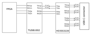
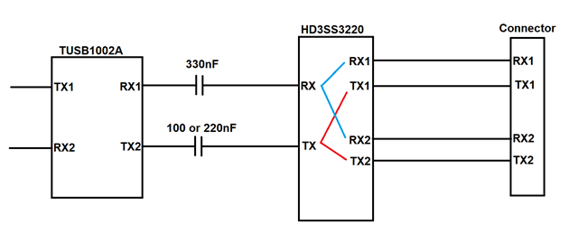
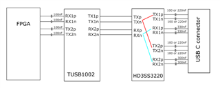
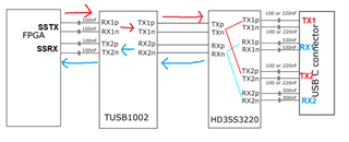
I am using the TUSB1002 and the HD3SS3220 in a SuperSpeedPlus (10Gbps) application which connects an FPGA via the TUSB1002 and  HD3SS3220 to a USB C connector. The attached image shows the connections along with AC decoupling capacitors. Could you review the way I have connected this and let me know if I need to make any changes for correct operation. Also, if I use the TUSB1002A will the connections still be the same.

Thank you,

Liam

  • Hi Liam,

    You've got a good start here but there are a few issues I see with your AC coupling capacitors.

    1. You should not AC couple both sides of the MUX on the TX lines as the total capacitance will fall below the 75nF limit on a USB3 line. You should choose whether to AC couple between the HD3SS3220 and the 1002 or between the HD3SS3220 and the USB-C connector, but not both. 

    2. Use 0.33uF capacitors between the HD3SS3220 and the USB-C connector on the RX lines. Only the TX path should use 0.1uF near the connector.

    3. You should AC couple the 1002 on the connection to the FPGA. Use 0.1uF capacitors on both the TX and RX lines here. If you already have these on the FPGA side, then you do not need to add more.

    I made a diagram to help show the connection:

    if I use the TUSB1002A will the connections still be the same.

    Yes

    Best,

    Shane

  • Hi Shane,

    I’ve changed my schematic to account for your suggestions -  see attached. Note we are using the TUSB1002A as part of a UFP arrangement: it is used in a device implementation.

    1 The HD3SS3220 is DC coupled to the TUSB1002A and I assume that the HD3SS3220 gets it bias from the TUSB1002A common mode voltage. The connections between the HD3SS3220 are AC coupled to the USB C connector. I think this is a better option because I am not sure if the host common mode voltage would exceed the HD3SS220 specs.

    2 I have used 330nF on the RX lines and 200nF or 100nF on the TX lines between the HD3SS3220 and USB C connector. Could you explain why there is a choice of either using 220nF or 100nF on the TX lines?

    3 The TUSB1002A connection is now AC coupled to the FPGA via 100nF caps. On your diagram RX1 and TX2 are connected from the TUSB1002A to RX and TX on the HD3SS220. I have shown RX2 and TX1connected from TUSB1002A to HD3SS220 as this was the implementation on an evaluation board we used in development. Is this arrangement ok?

    Thanks,

    Liam

  • Hi Liam,

    1. The connection looks good

    2. This is correct. There is a choice in the capacitor value because the USB spec states the USB3 total line capacitance must be between 265nF - 75nF. This gives some options in the capacitor value you use on the transmitting (TX) lines. 100nF and 220nF are the most commonly used values.

    3. The AC coupling looks good. Your arraignment is ok. Just be sure you connect the right pins on the Type-C connector and the USB host on your FPGA:

    I can review your schematic/layout when the design is further along if you'd like. Let me know if you have any questions in the meantime.

    Best,

    Shane

  • Hi Shane,

    Is it important where the ac coupling caps are placed? It would make the layout easier if the caps from the FPGA to the TUSB1002A could be placed near the TUSB1002A and the caps between the HD3SS3220 and USB C connector could be placed near the HD3SS3220.

    Thank you,

    Liam

  • Hi Liam,

    I recommend leaving some room between the 1002A pins and your AC capacitors. Placing the capacitors too close to the 1002A can cause signal reflections from the capacitor pad to reach back to the 1002A.

    If you leave at least 200mils between the 1002A and the AC capacitors, this reflection shouldn't cause issues. I recommend leaving ~200mils between the HD3SS3220 and the capacitors on the other side as well.

    Best,

    Shane

  • Thnak you Shane