This thread has been locked.

If you have a related question, please click the "Ask a related question" button in the top right corner. The newly created question will be automatically linked to this question.

TCAN11625-Q1: Questions about can transceiver test methods

Part Number: TCAN11625-Q1

Tool/software:

1、Module test method

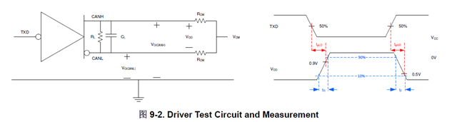
During module testing, see Figure 9-2. Driver Test Circuit and Measurement in the ti specification to see whether it means that no external can tool is used for testing. In the actual test process, do we need an external tool such as PCAN in order to better simulate the characteristics of the signal on the whole bus, and then the signal test.

2、Module test content

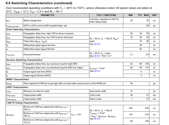
When doing module testing, what do we test content include? Do I need to test only the Driver Switching Characteristics or do I need to test both Driver Switching and Receiver Switching? If it's all about testing, where's the Receiver coming from?

Thank you for your reply!

  • Hello,

    I don't think a tool like PCAN is needed for that test. You can simply use an oscilloscope to capture the CAN signal, and use a function generator as TXD input.

    Doing both driver and receiver switching time test would be helpful, when you transmit some data on TXD, the RXD pin will just reflect whatever the transceiver see on CAN bus and interpret into digital output. So when you can do both driver and receiver switching test on a single module, what you see from receiver is your input to driver. I would also recommend to test total loop delay, this measurement describes the practical signal delay accounting for both driver and receiver delay. 

    Regards,

    Sean