This thread has been locked.

If you have a related question, please click the "Ask a related question" button in the top right corner. The newly created question will be automatically linked to this question.

DP83825I: Replacing DP83848 Questions on Transformer/transformer-less design

Other Parts Discussed in Thread: DP83848T

Tool/software:

Hi,

I am building a UAV Flight Controller based loosely on the Pixhawk Open Standards but I have some queries regarding a change in ethernet PHY and how to setup the transformer/Magnetics properly. I currently have success talking to certain ethernet devices, but some refuse to talk/get an ip.

The Standard I am following can be found here: https://github.com/pixhawk/Pixhawk-Standards/blob/master/DS-010%20Pixhawk%20Autopilot%20Bus%20Standard.pdf With the example Ethernet PHY on page 18 but also here:

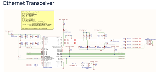
In my application I am using an STM32H743 connected over RMII to a different PHY, the DP83825IRMQR (Rather than the examples DP83848T). It mostly follows the example in the open standard for the magnetics. 

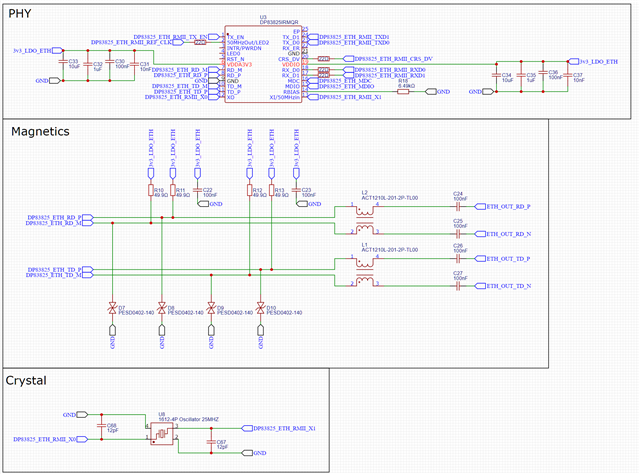
My question is about magnetics/transformers. It looks like the open standard is using a transformer-less design, which I copied but I am having some connectivity issues with some devices. 

1) Should I be using a transformer-less design with the DP83825? I am trying to keep component size/count to an absolute minimum.

2) I am using discrete transformers for the CMC, what should I do about center taps that would otherwise be there?

3) I have noticed that the devices it doesn't work with do not have their centre taps connected to anything either, could this be a cause?

  • Hi Conrad,

    Thanks for the detailed query.

    I will review with team and get back to you with feedback tomorrow.

    Thank you,

    Evan

  • Hi Conrad,

    1) Transformer-less operation is an option for DP83825, however the tradeoff here is reduced EMC/EMI performance due to lack of isolation. What are the EMC/EMI requirements for this design?

    2) Discrete CMC is acceptable, this should not be a concern. However, there should not be pull-ups on the MDI line as DP83825 is a voltage-mode driver. Please remove these resistors.

    3) I suspect pull-ups on the line to be the cause here, please test with them removed.

    Thank you,

    Evan

  • Hi Evan, 

    1) Pretty low, the total length of connections between transformers is going to be a maximum of 10cms, although it will be in close proximity (2-4cm) to some fairly noisy motor drivers. Would it be better to use a transformer and no CMC, or stick to transformer-less and maintain the CMC?

    2) Good to hear. So my setup will end up looking something like this?

    3) Excellent, I'll attempt to de-solder them and check my results!

    4) Do I need to set the strap options to select the correct drive mode/magnetics/transformer?

    Many Thanks

  • Ok Just to follow up my last questions, I have de-soldered the pull ups and it does now work! Many thanks for pointing me directly at the problem!

  • Hi Conrad,

    Thanks for confirming this resolved your issue!

    Regarding your questions:

    1) I recommend CMC for isolation if there are sources of EMC/EMI nearby.

    2,3) Looks good!

    4) No, voltage/current mode driver is inherent to the PHY. For future reference, "Application and Implementation" section of our PHY datasheets will clarify the recommended termination network on the MDI lines.

    Considering this issue closed for now, please open a new thread if you have further questions.

    Thank you,

    Evan