Part Number: TUSB216
Tool/software:
Hi team.
I have many questions about this device. Can we have a call to discuss?
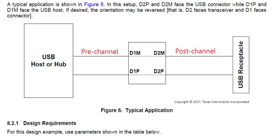
- What's the meaning of Host/Device agnostic in page 1?
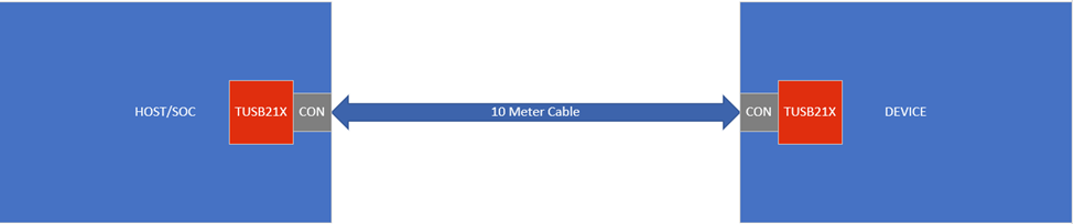
- In page 1, TUSB216 can supports up to 10-m cable length with two TUSB216 devices. What's the topology look like?
- Can you illustrate the daisy chain?

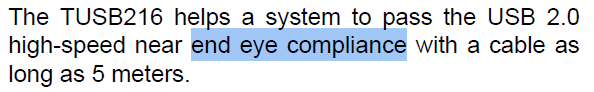
- What's end eye compliance?
- Should the power supply of I2C be earlier than VCC of TUSB216?

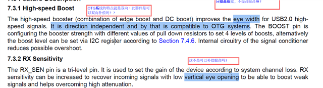
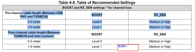
- Boost can only improve eye width and RX sensitivity can only improve both eye width and eye height. Correct? Why?
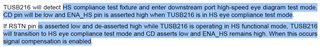
- Could you please explain more about this test?

- Could you please explain more about this?

- Could you please explain more about this?

- Could you please explain more about this?

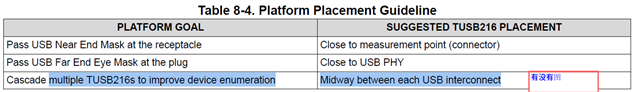
- Could you please share the diagram of below placement?
Nison