This thread has been locked.

If you have a related question, please click the "Ask a related question" button in the top right corner. The newly created question will be automatically linked to this question.

DP83TG720S-Q1: DP83TG720S Remote Sleep Exit does not seem to work

Part Number: DP83TG720S-Q1
Other Parts Discussed in Thread: DP83TG720EVM-MC

Tool/software:

I'm trying to get sleep and wakeup working on our device which uses a DP83TG720S PHY.

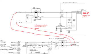
The PHY is configured as a slave, VSLEEP is powered from 3.3V, INH is connected to the power supplies.

The transition "Normal to Sleep" is working as expected.

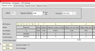
I write register 0x018B = 0x180, then set WAKE pin low.

As soon as I disconnect the ethernet or put the link partner PHY into reset, the PHY goes into sleep, INH goes low, and the power supplies turn off.

However, I'm unable to get the remote sleep exit to work.

I'm using a DP83TG720EVM-MC board as a link partner configured as a master, which should be sending the "Send-S" pattern by default.

Even if I put the link partner into "Send-T" by writing to reg[0x0405]=0x7400, reg[0x0509]=0x4007 and reg[0x0576]=0x0500 with the DIEP tool, my PHY does not wake up.

In this state, I can however wake up the PHY by pulling the WAKE pin high.

So it looks like local sleep exit is working, but remote sleep exit is not working.

Any hints why the remote sleep exit is not working?

  • Hi Felix,

    Let me try to replicate this in my lab and get back by end of week.

    Thanks,

    David

  • Hi Felix,

    I tested this in lab and am able to see INH go high when connecting to a transmitting master mode PHY (Note this PHY must be in autonomous mode, not managed mode). What length Ethernet cable are you using? Please use a short cable (<2m) and let me know the results.

    Please also share your schematic.

    Thanks,

    David 

  • Hi David,

    thanks for supporting!


    I tried to replicate your result by connecting two DP83TG720EVM-MC boards, but I cannot replicate your results.

    Here's my setup and steps taken:

    Board 1: J2 set to "bottom" position to select master mode, all dip switches "up" / 1111

    Board 2: J2 set to "up" position to select slave mode, all dip switches "up" / 1111

    Each board connected to PC with a USB cable (J18), both boards connected to each other via J5 and Rosenberger H-MTD cable

    Link is up (LED D3 on master on, LED D4 on slave on)

    Connect to slave board with DIEP tool, set register 0x018B to 0x0180

    Set wake pin low by moving jumper J3 to the "right" / GND position

    Disconnect AE cable

    INH pin / J6 stays high


    Even if I try the "local sleep entry for Slave mode phy" approach, IHN stays high:

    Set register 0x018B = 0x0080, 0x042F = 0x0007, 0x041E = 0x0100, wake pin low -> IHN stays high


    So I'm seeing different result between our custom board and the evaluation board:

    With our custom board, I can get sleep to work / INH goes low, but remote sleep exit doesn't work

    And with the evaluation board, I can't even get sleep entry to work (INH stays high)


    I'm surprised to see that on the evaluation board, IHN has a pull-up (R102 2.2k), while the data sheet specifies a 10k pull-down


    Could you share the steps you took to test the sleep and wakeup behaviour?


    Attached is a snippet of the PHY and surrounding circuitry from our schematic

    For the tests I performed, R931 is not populated, and R977 is populated

    Thanks,

    Felix

  • Hi Felix,

    The DP83TG720EVM-MC is not set up to evaluate wake/sleep performance unfortunately, as you have seen the INH signal does not have the proper pull down, and does not disconnect the supplies. 

    I believe the issue may lie in the non-standard MDI design which is being used, which looks quite different than the recommended circuit given in section 8.2 of the datasheet. Is the Common Mode Choke not populated during these tests? Can you share the adapter schematic as well so I can see the DC blocking capacitors and common mode termination?

    I can share with you DP83TG721EVM's which have our fully TC-10 compliant DP83TG721 PHY on-board. This PHY is interoperable with other vendors PHYs as the TC-10 protocol is standardized. From the looks of your schematic, it seems DP83TG721 was already designed to be populated, is this correct?

    Thanks,

    David

  • Hi David,

    if I modify the EVB board to put a pull-down on the INH line instead of a pull-up, I should be able to test at least the behaviour of the INH pin (without turning the supplies off), right?

    Here's a snippet of the MDI design on the adapter - we have different configurations, but always populate only one common mode choke. All in all, we match the recommended circuit very closely.

    Yes, we prepared support for the '721 variant for a future revision - but so far, we haven't been able to get documentation, samples, pricing or dates as the chip has not been publicly available. Please do share anything you can, like the EVB schematics.

    Regardless, we still need to get remote wakeup working with our current design and the '720.

    Thanks,
    Felix

  • Hi Felix,

    I do not quite understand the MDI portion of the design, can you help by annotating the below? In regards to validating the MDI, is link up stable and data throughput functional? Have you performed PMA compliance testing?

    The 720 will not enter sleep mode until core supplies are cut off. You would be able to see INH go low on the EVMs with INH pulldown modification, however it would not go high again until supplies are cut off before remote wake signal is received.

    Please let me know about the length of the cable being used as well. Please try with a short cable (<1 meter) as well.

    The 721 chip is publicly available on ti.com now. Please send me a private message and I will provide the latest documentation, pricing, etc.

    Thanks,

    David    

  • Hi David,

    yes, the MDI portion is exactly as you annotated it - the two sections are connected by a B2B connector, and CO201 is the board to cable connector. Link is stable, data throughput at close to 1Gbps. We haven't performed PMA compliance testing, but have seen no link quality issues.

    Our cable length is approximately 1m for this test. I can try something even shorter.

    Thanks, Felix

  • Hi Felix,

    As I cannot see the power section of the schematic, I want to confirm with you that INH is in fact cutting off all supplies other than Vsleep. Can you confirm that once INH goes low, that VDD1P0, VDDA, VDDIO are all cut off and only Vsleep remains? As mentioned, the 720 will not fully enter sleep mode until all supplies except for Vsleep are cut off. Perhaps you could share the full schematic over email.

    Thanks,

    David