This thread has been locked.

If you have a related question, please click the "Ask a related question" button in the top right corner. The newly created question will be automatically linked to this question.

TLK10232: SFP 1000BASE-X using 1G-KX with AN and LT disabled and dataswitch

Part Number: TLK10232

Tool/software:

Hello,

We are using TLK10232 in one of our designs, which can be summarized with the next diagrams:

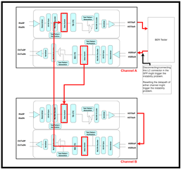
Mode of operation 1 (10GBASE-R):

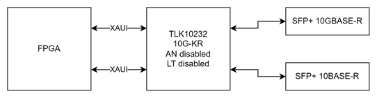
We managed to make this mode work by finding the most suitable equalization parameters for our system, after following the bringup procedures.

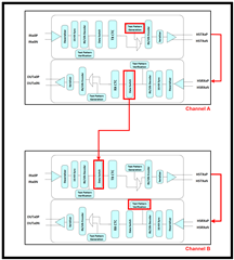
Mode of operation 2 (1000BASE-X):

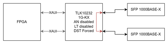
In this mode we don't need to pass through the FPGA, so we thought that the fastest way to achieve 1000BASE-X regeneration was to enable the DST switch setting the reserved bits 30.23.4:0 (DST_FORCE_SEL) to 0b11000. This sets the dataswitch configuration like the next image:

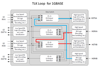
The LS side would be unused, although the FPGA might be driving the LS lanes (IN) with XAUI data.

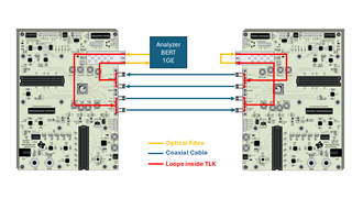
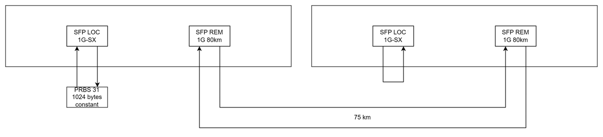
We are struggling to make this mode work reliably. We can leave a test (see image below) for 60+ hours with no issues, but if we disconnect/connect the LC connectors in any of the SFP modules several times, the system ends up not being able to leave KX_RX_FAULT state and the communication is broken.

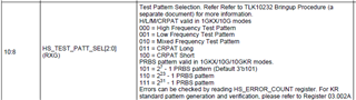
We have monitored HS_CHANNEL_STATUS_1 (30.15) register and we see the next values:

HS_DECODE_INVALID 1

HS_CHANNEL_SYNC 0

KX_RX_FAULT 1

Most of the time we solve the problem by issuing a datapath reset, but it isn't guaranteed to work always.

Any idea on what could be causing the issue?

  • Hi Manuel,

    I'm looking into this and will get back to with further feedback by COB tomorrow.

    Best,

    Lucas

  • Hi Manuel,

    Is the ST pin pulled high for Clause 22 operation? This is a requirement to use 1G-KX mode with AN disabled.

    Can you share your register write sequence to configure your 1G-KX mode of operation? Can you additionally share your hardware configuration on the ST, MODE_SEL, PRBSEN, and REFCLK_SEL pins?

    Best,

    Lucas

  • Hi Lucas,

    We are applying the following configuration for 1G-KX mode of operation, based on the Bring Up Procedures VER 2.0 (Preliminary)

    Device Pin Settings

    o ST input pin is Low (we had tried to pulled high for Clause 22 operation but communication does not rise)
    o MODE_SEL input pin is Low
    o PRBSEN input pin is Low

    Reset Device

    o Hard Reset: RESET_N asserted for at least 10 us

    Mode selection

    o Write 1’b1 to 30.0.11 GLOBAL_WRITE
    o Write 1’b0 to 30.1.10 SW_DEV_MODE_SEL
    o Write 1’b0 to 30.1.11 SW_PCS_SEL
    o Write 1’b0 to 1.150.1/30.150.1 LT_TRAINING_ENABLE
    o Write 1’b0 to 7.0.12 AN_ENABLE

    HS Serdes settings

    o Write 1’b0 30.4.15 HS_ENTRACK
    o Write 0x03 30.4.14:12 HS_EQPRE[2:0]
    o Write 1’b1 30.4.6 HS_PEAK_DISABLE
    o Write 0x0 30.4.11:10 HS_CDRFMULT[1:0]
    o Write 0x2 30.4.9:8 HS_CDRTHR[1:0]
    o Write 0x6 30.3.15:12 HS_SWING[3:0]
    o Write 1’b1 30.32801.4 SYNC_STATUS_CHECK_DISABLE

    Data Switch and Issue Data path Reset

    o Write 0x30 30.23.4:0 DST_FORCE_SEL[4:0]
    o Write 1’b1 to 30.14.3
    o Write 1’b0 to 30.0.11 GLOBAL_WRITE

    As I mentioned at the beginning, we are using the preliminary version of the Bring Up Procedures.
    Is there a more recent or definitive one?

    Regards,

    Sofia

  • Hi Sofia,

    Thank you for sharing your register configuration. The Bringup Procedures document has not been updated since v2 preliminary version.

    1. I noticed you are not configuring DSR_FORCE_SEL. Can you try writing 30.25.4:0 = 1b11000 after writing to DST_FORCE_SEL?
    2. Can you confirm that the REFCLK_SEL pin is pulled low, input reference clock frequency is 156.25 MHz, and register 30.29 = 0x0000 (default value)?
    3. How did you select the values you are using in registers 30.3 and 30.4? Was testing performed sweeping different EQ configurations?

    Best,
    Lucas

  • Hello Lucas,

    We made the next modifications:

    1. Switch to clause 22.
    2. Set DSR_FORCE_SEL as you said (1b11000, same as DST_FORCE_SEL).

    After these changes the solution is still not reliable enough. We manage to get the TLK stuck after several unplug/plug of the LC connectors. When the communication is broken, at least one of the channels reports the following permanently:

    RX_FIFO_OVERFLOW = 1 (In 1GKX mode, indicates receive FIFO is reset)
    TX_FIFO_OVERFLOW = 1 (In 1GKX mode, indicates transmit FIFO is reset)
    HS_DECODE_INVALID = 1
    HS_CHANNEL_SYNC = 0

    HS_PLL_LOCK, HS_AGC_LOCKED, HZ_AZ_DONE and HS_LOS flags are ok.

    Regarding the two other points you mentioned:

    2. I can't find such pin in this package, but I can confirm that register 30.29 = 0x0000 and we are driving REFCLK0 with a 156.25 MHz clock.

    3. We did the EQ sweep for the 10G configuration. For 1G we are using the same values, since they worked just fine for 60+ hours. Do you think we should run another EQ sweep for 1G anyway?

    Regards,

    Manu.

  • Hi Manu,

    Thanks for the update on this.  Lucas is out of office early this week, but can get back to you on this later this week.

    Thanks,

    Drew

  • Hi,

    We are trying to make progress with the EQ parameters sweep for RX in the meanwhile. There are a few questions we'd like to clarify:

    1. The datasheet states that 1G-KX mode has CRPAT and high/low/mixed pattern generation, although the verifier only supports CRPAT. The bringup procedure lists PRBS patterns available for selection and states nothing about PRBS patterns not being available for the verifier. It's not clear for us if PRBS is available for both the generator and the verifier.

    From the datasheet, under 1G-KX mode functional description:

    4.5 Test Pattern Generator
    In 1G-KX mode, this block can be used to generate test patterns allowing the 1G-KX channel to be tested
    for compliance while in a system environment or for diagnostic purposes. Test patterns generated are
    high/low/mixed frequency and CRPAT long or short.


    4.6 Test Pattern Verifier
    The 1G-KX test pattern verifier performs the verification and error reporting for the CRPAT Long and Short
    test patterns specified in Annex 36A of the IEEE 802.3-2008 standard. Errors are reported to MDIO
    registers.

    And the bringup procedure, under KX with Auto Negotiation disabled, HS / LS Test Patterns, with 156.25 MHz / 312.5 MHz Refclk:

    o Select HS test pattern
        2^31 – 1 PRBS pattern – Write 3’b111 to 30.11.10:8
        2^23 – 1 PRBS pattern – Write 3’b110 to 30.11.10:8
        2^7 – 1 PRBS pattern – Write 3’b101 to 30.11.10:8
        High Frequency – Write 3’b000 to 30.11.10:8
        Low Frequency – Write 3’b001 to 30.11.10:8
        Mixed Frequency – Write 3’b010 to 30.11.10:8
        CRPAT Long – Write 3’b011 to 30.11.10:8
        CRPAT Short – Write 3’b100 to 30.11.10:8
    o Enable KX HS test pattern generation
        All Patterns – Write 1’b1 to 30.11.13
    o Enable KX HS test pattern verification
        Note: HLM Frequency verification not supported
        All Other Patterns – Write 1’b1 to 30.11.12

    We understand that only CRPAT long and short can be generated and verified using TLK10232 in 1G-KX mode with no additional equipment.

    2. We only need to test the HS side, since we are enabling the Data Switch to route traffic from one HS channel to the other (the block diagram shows that the data switch is after the pattern generation and verification, so it should not interfere in the test). So we are not enabling any LS test pattern at all. The bringup procedure says that we need to do this in order to clear the error counters:

    Clear Error Counter
        CRPAT Long/Short – Write 1’b1 to 30.11.6 and Write 3’b011 to {30.11, 30.11.5:4}
        All Patterns – Read 30.16 HS_ERROR_COUNTER to clear

    The instruction in bold is telling us to write LS test pattern registers (LS_TP_VERIFY_EN and LS_TEST_PATT_SEL). Is this actually needed to clear the error counters for a HS test?

    3. Is Link Training disabled by default in 1G-KX mode? How is it disabled using clause 22.


    So far we have performed a test following the next procedure:

    1. Set ST pin to 1 (clause 22) and set MODE_SEL pin to 0 (1G mode).

    2. Reset using reset pin. Sleep for 1000ms.

    3. Write 0 to SW_DEV_MODE (30.1.10) and SW_PCS_SEL (30.1.11) in CHANNEL_CONTROL_1 register for both channels.

    4. Select test pattern writing 011 to 30.11.10:8 (CRPAT Long).

    5. Enable test pattern generation and verification writing 1 to 30.11.12 and 30.11.13.

    7. Sweep sync_status_check_disable, cdrfmult, cdrthr, h1cdrmode, pkdisable, entrack, eqpre (we are skipping AGC control). For every set of parameters we do the next steps:

    1. Write the configuration. Issue a datapath reset and sleep for 1000ms.

    2. Wait until HS_TP_STATUS (30.15.15) is 1.

    3. Read CHANNEL_STATUS_1 register (30.15) once to clear any latched value.

    4. Read CHANNEL_STATUS_1 register (30.15) every 1ms and accumulate the flags hs_errors, pcs_tp_errors, hs_pll_errors, hs_los_errors, hs_az_errors, hs_sync_errors, hs_agc_errors, each one in an independent variable. We also monitor TX/RX FIFO over/underflow, although we don't consider these flags to discard a config.

    5. Sweep to next parameter set once 20 minutes have elapsed of 50 errors are read in any of the variables in the previous step.

    Using this method we find several combinations that give us no errors. But I find it suspicious that not a single set is reporting HS_ERRORS. Are we doing this correctly?

    Regards.

    Manu.

  • Hi Manu,

    Regarding REFCLK_SEL pin: You're correct, TLK10232 does not include this pin, reference clock selection is done with register 30.29. Sorry for my mistake.

    Regarding patterns in 1G-KX mode: All test patterns should be supported by the internal HS generator and verifier in 1G-KX mode.

    Regarding clearing CRPAT errors: It is not necessary to write LS register bits to clear the HS error counter.

    Regarding link training in 1G-KX mode: Link training should be disabled by default.

    Regarding EQ Sweep: My recommendation is to select a PRBS pattern and check for errors in the HS_ERROR_COUNTER register.

    Best,

    Lucas

  • Hi Manu,

    I discussed this case with my colleagues and we came to the conclusion that this issue likely cannot be resolved without a datapath reset. Repeatedly plugging/unplugging LC connectors can cause transient characteristics to be present at the optical module, resulting in odd signal behavior at the TLK receiver during initialization. This can cause issues for the device bringup and we recommend maintaining a stable signal at the input or issuing a reset to restart initialization.

    Best,

    Lucas

  • Hi Lucas,

    Thank you very much for your research.

    A few days back we were afraid that that might be causing the issue, so we decided to implement an automatic datapath reset based on SFP LOS/TLK LOS events. Unfortunately, we couldn't reach a stable solution using this approach.

    Sometimes, more than one datapath reset was needed to reestablish the link. If two of the devices were connected (like in the last diagram of my first post), they could trigger datapath resets between each other, leading to an oscillating behavior that could take an unpredictable amount of time to stabilize.

    We tried to find the best condition to trigger the datapath reset (SFP LOS, PLL LOCK, KX_RX_FAULT, and others). I can't remember if we tried to use SFP LOS alone, since that could be the best flag to detect the transient you mention. Will run a few tests and report the results to you.

    Is this an issue that only affects the 1G-KX mode? We are unable to reproduce the problem in 10G-KR mode.

    Besides the datapath reset issue, I can't manage to run a test properly. I can't find a single configuration that reports hs_errors. All configurations leave the TLK unable to achieve HS_CHANNEL_SYNC and HS_AGC_LOCKED using PRBS31.

    We tried the EQ suggested in other threads for SFPs (ENTRACK_EN = 1 and EQPRE = 0x05) and left a test running for +17 hours with no errors. So we have, at least, 2 completely different configurations that can run without errors for hours (the other is the one posted by Sofia). I don't understand why I can't make those configurations work in CRPAT/PRBS31 patterns.

    Anyway, since this doesn't seem to be related to the EQ parameters, I will go back to focus on the datapath reset approach.

    Regards,
    Manu.

  • Hello,

    We have tested the datapath reset approach by checking the SFP LOS signal for both channels. If any of the channels changes from LOS condition to no LOS condition, we reset the datapath.

    So far, the results are promising for low dispersion channels (from short SMF to 25 km). We are not so lucky for longer channels (up to 80 km). I am afraid that we need to stress on the EQ parameters.

    Unfortunately, as I mentioned earlier, I think we must be doing something wrong setting up the sweep (although we achieved it in 10G-KR). Let me post our procedure to sweep EQ parameters using PRBS31:

    1. Set ST pin to 1 (clause 22) and set MODE_SEL pin to 0 (1G mode).

    2. Reset using reset pin. Sleep for 1000ms.

    3. Write 0 to SW_DEV_MODE (30.1.10) and SW_PCS_SEL (30.1.11) in CHANNEL_CONTROL_1 register for both channels.

    4. Select test pattern writing 111 to 30.11.10:8 (PRBS31).

    5. Enable test pattern generation and verification writing 1 to 30.11.12 and 30.11.13.

    7. Sweep sync_status_check_disable, cdrfmult, cdrthr, h1cdrmode, pkdisable, entrack, eqpre (we are skipping AGC control). For every set of parameters we do the next steps:

    1. Write the configuration. Issue a datapath reset and sleep for 1000ms.

    2. Read CHANNEL_STATUS_1 register (30.15) once to clear any latched value.

    3. Read CHANNEL_STATUS_1 register (30.15) every 1ms and accumulate the flags hs_errors, pcs_tp_errors, hs_pll_errors, hs_los_errors, hs_az_errors, hs_sync_errors, hs_agc_errors, each one in an independent variable. We also monitor TX/RX FIFO over/underflow, although we don't consider these flags to discard a config.

    4. Sweep to next parameter set once 20 minutes have elapsed of 50 errors are read in any of the variables in the previous step.

    Not a single combination of parameters passes the test. All of them are skipped after 50 errors in AGC_LOCKED or HS_SYNC_STATUS. None of them increase HS_ERRORS_COUNTER.

  • Hi Manu,

    Is this an issue that only affects the 1G-KX mode? We are unable to reproduce the problem in 10G-KR mode.

    I believe it can be possible in both 1G-KX mode and 10G-KR mode. Perhaps repeatedly plugging/unplugging LC connectors creates more significant transients at 1G-KX rate than 10G-KR rate.

    For PRBS testing, it is necessary to enable SYNC_STATUS_CHECK_DISABLE. This allows for transmission without waiting for HS_SYNC_STATUS to be reached.

    Seeing HS_ERROR_COUNTER=0x0000 suggests there are no errors. HS_ERROR_COUNTER will default to 0xFFFD if the verifier is not detecting valid PRBS data.

    Best,

    Lucas

  • Seeing HS_ERROR_COUNTER=0x0000 suggests there are no errors. HS_ERROR_COUNTER will default to 0xFFFD if the verifier is not detecting valid PRBS data.

    So we don't need to check for AGC_LOCK or PLL_LOCK during the sweep? I don't understand how several configurations can achieve CHANNEL_STATUS_1 = 0x1c03 using an external PRBS tester but, if I run the PRBS using TLK, I can't find any config that can achieve AGC_LOCK. Not even with a short SMF link.

    I'm unable to verify the 0xFFFD value. If I disconnect the fiber during the test, the channel no longer receives any pattern, but HS_ERROR_COUNTER doesn't go to 0xFFFD. It's still 0.

    For PRBS testing, it is necessary to enable SYNC_STATUS_CHECK_DISABLE. This allows for transmission without waiting for HS_SYNC_STATUS to be reached.

    Yes, we are already doing that.

    Edit: We saw that theres is a pin called PRBS_EN. Is it needed to set this pin to 1 for HS_ERROR_COUNT to report PRSB errors? It's not mentioned in the bringup procedure.

  • Hi Manu,

    Yes, can you try pulling PRBS_EN pin high?

    Best,

    Lucas

  • Hello Lucas,

    We managed to run a test using a Viavi MTS-5800 tester for 12 days with no errors. We assume that the equalization is fine. However, we are still dealing with the inestabilities caused from unplugging and plugging the fiber.

    Resetting the datapath does not give us any certainty, since sometimes it takes 1 datapath reset and sometimes 7 to restore the link. Hard resetting the IC and doing the provisioning from scratch give us the same result.

    What's more concerning is that after restoring the link using the datapath resets, the link seems unstable and can lead to one of the channels being stuck in the 0x1903 status (CHANNEL_STATUS_1 register) at random times (HS_DECODE_INVALID and !HS_CHANNEL_SYNC). The channel transmits data, but the Viavi tester sees constant bit errors.

    We've also tried to do datapath resets when the channels are running fine, just to check if we always recover the link. That's not happening either. We don't recover the link always, just like when we unplug and plug the fiber. In this scenario the TLK is not seeing any transcient (at least from the media perspective).

    At this point we are not really sure if we can get to a reliable product.

  • Hi Manu,

    Thanks for the update.  Lucas is on business travel this week, so there may be delayed responses on this.

    For these cases where you issue a datapath reset and are unable to consistently recover the link, is this issue limited to higher dispersion, or do you see this for lower dispersion channels as well?

    Thanks,

    Drew

  • Hi Drew,

    This is happening with low dispersion channels as well. I tried using a short SMF link (a few centimeters) with a 5dB/10dB attenuator at the input of a 1550nm SFP with a reach of 80km.

    Thank you,

    Manu.

  • Hi Manu,

    Thanks for clarifying this.

    Another question: Have you investigated using the data switch without using the DST/DSR_FORCE_SEL?

    Thanks,

    Drew

  • Hi Drew,

    Yes, we tried using the non reserved bits to set up the DST/DSR and it worked fine, but I think that the on/off conditions were triggering the activation/deactivation of the switch against our will.

    If I remember correctly, we were able to activate the DRS/DST but it got automatically deactivated if we stopped the traffic from the tester. We found another post that suggested using the DST/DSR_FORCE_SEL (https://e2e.ti.com/support/interface-group/interface/f/interface-forum/592110/tlk10232-channel-switch-function-doesn-t-work-well/) and decided to go with that approach.

    We need the switch to be enabled no matter what.

    Thank you,

    Manu.

  • Hi Manu,

    Thanks for clarifying this.  We need some time to look into this further before providing additional suggestions.  I expect we can get back to you next week with additional suggestions.

    Thanks,

    Drew

  • Hi Manu,

    Sorry for the delay on this case. I re-reviewed all of the information that you shared with us and I'd like to ask for some clarifications.

    1. I understand that the link becomes unstable after issuing a datapath reset. Does this issue only occur when you operate in 1G-KX mode? Or does it also occur when you operate in 10G-KR mode?
    2. I believe several changes have been made since the last time you shared your register configuration sequence. Can you share this sequence again so I can review your settings? Can you share the sequence used for both 1G-KX mode and 10G-KR mode?
    3. Can you share which pin settings are now being used in both 1G-KX mode and 10G-KR mode? I'm specifically interested in the ST, MODE_SEL, and PRBSEN pins.

    Best,

    Lucas

  • Hello Lucas,

    Nice to hear from you again.

    1. Starting from a stable communication, the link may become unstable when unplugging and plugging the LC connector of the 1000BASE-LX SFP, or after issuing a datapath reset. After losing the link, issuing a datapath reset does not guarantee the recovery of it. Only after several attempts, based on CHANNEL_STATUS_1 register, we recover the communication. If there are 2 TLK10232 involved in the communication, we can't predict the result, since issuing a datapath reset in one TLK10232 may affect the stability of the TLK10232 in the other end, leading to an oscillating behaviour between the two. This never happens in 10G mode. As stated before, we have this problem with low and high dispersion channels at 1G.
    2. We are using the following initialisation sequence (pins and registers):

    1G Mode (Once the link is up, we can run BER tests for several hours without errors over low and high dispersion channels):

    1. Set ST pin to 1.
    2. Set MODE_SEL to 0.
    3. Set RESET_N to 0, sleep 10 us, set RESET_N to 1.
    4. Sleep 1000 ms.
    5. Set SW_PCS_SEL and SW_DEV_MODE_SEL bits to 0 in CHANNEL_CONTROL_1 register for both channels.
    6. Set GLOBAL_WRITE_EN to 1 in GLOBAL_CONTROL_1 register.
    7. Set HS_ENTRACK_EN to 1 in HS_SERDES_CONTROL_3 register.
    8. Set EQPRE to 3 in HS_SERDES_CONTROL_3 register.
    9. Set HS_PEAK_DISABLE to 1 in in HS_SERDES_CONTROL_3 register.
    10. Set HS_CDRMULT to 0 in HS_SERDES_CONTROL_3 register.
    11. Set HS_CDRTHR to 2 in in HS_SERDES_CONTROL_3 register.
    12. Set HS_SWING to 660 mVpp in HS_SERDES_CONTROL_2 register.
    13. Set SYNC_STATUS_CHECK_DISABLE to 1 in MC_AUTO_CONTROL register.
    14. Set DST_FORCE_SEL to 8 in DST_CONTROL_1 register.
    15. Set DSR_FORCE_SEL to 8 in DSR_CONTROL_1 register.
    16. Issue datapath reset.
    17. Sleep 1000 ms.
    18. Set GLOBAL_WRITE_EN to 0 in GLOBAL_CONTROL_1 register.

    10G Mode:

    1. Set ST pin to 0.
    2. Set MODE_SEL to 0.
    3. Set RESET_N to 0, sleep 10 us, set RESET_N to 1.
    4. Sleep 1000 ms.
    5. Set SW_PCS_SEL bit to 1 and SW_DEV_MODE_SEL bit to 0 in CHANNEL_CONTROL_1 register for both channels.
    6. Set GLOBAL_WRITE_EN to 1 in GLOBAL_CONTROL_1 register.
    7. Set LT_TRAINING_ENABLE to 0 in LT_TRAIN_CONTROL register.
    8. Set AN_ENABLE to 0 in AN_CONTROL register.
    9. Set HS_ENTRACK_EN to 1 in HS_SERDES_CONTROL_3 register.
    10. Set EQPRE to 3 in HS_SERDES_CONTROL_3 register.
    11. Set HS_PEAK_DISABLE to 1 in in HS_SERDES_CONTROL_3 register.
    12. Set HS_CDRMULT to 0 in HS_SERDES_CONTROL_3 register.
    13. Set HS_CDRTHR to 2 in in HS_SERDES_CONTROL_3 register.
    14. Set HS_SWING to 660 mVpp in HS_SERDES_CONTROL_2 register.
    15. Set SYNC_STATUS_CHECK_DISABLE to 1 in MC_AUTO_CONTROL register.
    16. Issue datapath reset.
    17. Sleep 1000 ms.
    18. Set GLOBAL_WRITE_EN to 0 in GLOBAL_CONTROL_1 register.

    Regards,

    Manu.

  • Hi Manu,

    Thank you for sharing the issue conditions and your configuration sequence. I reviewed and didn't see any clear issues with the sequence you are using.

    I see 2 clear differences between your 2 modes of operation: 1G-KX versus 10G-KR mode and use of the data switch. At this time it's unclear to me if 1G-KX mode or the data switch configuration is the root cause of the issue, or if it's the combination of both of these. I've thought of an experiment you can run to determine which of these features is the root cause.

    Is it possible to use your 10GBASE-R SFP+ modules in the following configuration? I'd be curious to know if the issue occurs.

    Is it possible to use your 1000BASE-X SFP modules in the following configuration? I'd be curious to know if the issue occurs.

    Best,

    Lucas

  • Hi Lucas,

    The data switch being the root cause of the problem was one of our hypothesis a few weeks back, so we already did the first test you are proposing. We couldn't replicate the instability problem we see in 1G mode.

    To prepare the second configuration you mention we'd need a lot more time. Is it possible for you to arrange that setup using 2 evaluation boards in less time?

    Regards,

    Manu.

  • Dear Lucas,

    Just an idea to support the previous comment.

    We would suggest you please perform the following experiment. It is similar to our real setup. (The main difference is that we also have an optical path, instead of coaxial cables, in the communication between nodes).

    Note the red lines are performed as loops inside the TLK (data switch).

    For us it is quite difficult to get a working link with no errors. Even using only one TLK (half of the setup), it takes several reset attempts (in the datapath) and it is not deterministic. If we go to the real case with two TLKs, it is even more difficult, because apparently reseting in one side translates into losing the path in the other end TLK.

    In any case, once you are able to reach a stable link with no errors, please proceed in the following way: unplug and plug the fibre a repeted number of times. In our case, recovering the link looks random. We have to reset the datapath an unknown number of times until the TLKs at both ends recover the link.

    If you get the experiment running properly, also pluggin and unpluggin the fibre, we would appreciate to know your configuration parameters.

    Thank you,

  • Hi Manu,

    I understand that the issue was not reproduced when you used setup #1, suggesting the data switch configuration may not be the root cause. I also understand that setup #2 would take quite a bit of time and effort to setup.

    Unfortunately I cannot perform the experiment you outlined. I do not have necessary equipment available in my lab to use.

    • I do not have optical fiber, modules, or loopbacks.
    • I only have one TLK10232 EVM board.

    With the equipment I do have, I can try to reproduce the following behaviors. Please let me know if you believe these experiments will be helpful.

    • Check for BER stability after issuing a datapath reset in 1G-KX mode.
    • Use a HCB in the SFP cage. Check for BER stability after repeatedly plugging/unplugging the HCB.
    • Try to reproduce these issue with and without routing HS channel A to HS channel B internally.

    Best,

    Lucas

  • Hi Lucas,

    Do you have an external BER tester or another board that can work as such?

    This is our setup, in which we are able to replicate the issue using just one TLK:

    If you don't have any additional equipment to generate and check the PRBS pattern outside the EVM, this is the most similar setup that we can think of:

    But I'm not sure if the problem will show up under this conditions. As I explained in previous posts, we are not sure of being running the internal PRBS test properly in 1G mode, so I don't know if I can arrange this setup and get meaningful results:

    e2e.ti.com/.../5350451

  • Hi Manu,

    Yes I do have an external BER tester in my lab. Allow me to coordinate testing equipment so I can test the first setup you have shown. I'll get back to with the results of my bench test.

    Best,

    Lucas

  • Hello Lucas,

    Thank you very much for your time.

    Were you able to make progress with the test?

    Regards,

    Manu.

  • Hi Manu,

    Sorry for the delayed update.

    Due to the geometry of my HCB, I'm unable to test with this exact setup. The HCB blocks me from accessing HSRXBn.

    I made a small modification to the setup. I plan to use an electrical loopback on channel A and connect channel B to an external PRBS generator/checker. I can then attempt to reproduce the issue by resetting the datapath. Please let me know if you see any issues with this setup.

    I ran into some unexpected issues bringing up the system in 1G-KX mode. I'm still working through this and will need some additional time before I'm able to try reproducing the issue.

    Best,

    Lucas

  • Hello Lucas,

    Thank you very much for the update.

    The setup you arranged seems ok to me. You could try to reproduce the issue either by resetting the datapath or disconnecting/connecting the electrical loopback you have in the SFP slot. It might take several attempts to trigger the event.

    The only difference I can tell between your setup and ours is that we were using 1000BASE-SX and 1G 80km 1550nm SFPs in both channels. Our PRBS generators are Anritsu and Viavi, both configured to generate layer 2 traffic with PRBS31 payload and a 1000BASE-SX interface with autonegotiation turned off (forced to 1G full duplex).

    This is one of the reports we have after a 65 hours test:

    7268.report.pdf

    The configuration of the PRBS generator is detailed in the report. And the test was performed for the arrangement in the next picture:

    Looking forward to the results with your setup.

    Regards,

    Manu.

  • Hi Manu,

    Thank you for the confirmation on my setup, and providing additional details and report from your testing. I will continue 1G-KX bring-up with my setup.

    Best,

    Lucas

  • Hi Lucas,

    Do you have any update on this setup?

    Did you manage to get the 1G link working? Could you reproduce the issues mentioned by Manu? 

    Thank you,

    Fernando

  • Hi Fernando,

    Unfortunately I'm still working through some issues with my setup. We are currently undergoing an office + lab move in addition to holidays this week, so I won't have full lab access again until 12/16.

    Best,

    Lucas

  • Hi Lucas,

    I know it is a busy time but did you solve the issues you had with the setup? 
    Any update?


    Thank you!

  • Fernando

    Due to the US Christmas and New Year holiday, the response to your question will be delayed. Sorry for the wait and any inconvenience it may cause.

    Thanks,

    David

    Thanks,

    David