


Part Number: TSB41BA3F-EP
Tool/software:
Hi Team,
I am working with the TSB41BA3F-EP creating a board.
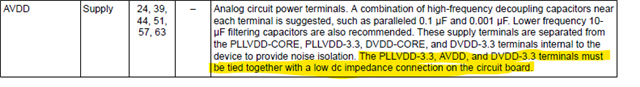
The datasheet states that AVDD, PLLVDD-3.3, and DVDD-3.3V need to be tied together:
and there isn't really a reference in the datasheet I can find about the ground plane connection - the pinout table seems to imply that there should be a single ground plane on the board - but I want to confirm that is true.
So with that - I have two questions:
1. Is it not recommended for this device to have separate analog and digital grounds for this device?
2. Also to confirm - the digital and analog supplies do not need to be separate for this device?
If separate grounds are not required or suggested and a single 3.3V power supply should be used for all 3.3V rails - why is this device able to do that, is there something special within the device or any reason why this wouldn't be suggested? I am a little new to this type of design and I was under the impression that analog and digital power should be separated for similar type devices - but what is presented in the datasheet is making me question that - so any help would be greatly appreciated here.
Thanks!
Parker Dodson
