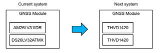
Other Parts Discussed in Thread: THVD1451, AM26LV31
Tool/software:
Hi team,
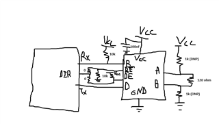
Is there any reference schematic for using this device as RS422 TX/RX.
Best regards,
Goto
This thread has been locked.
If you have a related question, please click the "Ask a related question" button in the top right corner. The newly created question will be automatically linked to this question.
Hi Clemens,
Let me modify my question.
Is it possible replace like below?
Also, It is helpful if there is reference design for using THVD1420 as RS422.
Best regards,
Goto
Your current system has eight unidirectional channels. Using the THVD1420 with the same signals would require eight chips in the module (four configured to always transmit, and four to always receive).
With full-duplex transceivers like the THVD1451, you would need only four chips.
Why do you want to replace the AM26LV31/DS26LV32AT?
Replace is because of reducing channels.
Actually, two drivers and one receiver are need, so I consider use three THVD1420s.
Also, system to be connected are different and half-duplex is enough.
Thank you.
Goto
RS-422 never is half duplex.
If a driver and a receiver share the same half-duplex bus, then you need only one RS-485 transceiver for them (two total).
Customer now uses half duplex AM26LV31 and DS26LV32 for RS422. This is not bidirectional.
Channel is reduced and they would like replace device with minimum system change.
So, THVD1420 is selected.
Is this mistake?
"Half duplex" means that the drivers and receivers are connected to the same bus lines, and that all modules control the driver enable signals so that at most one driver on the bus is active at the same time.
This is possible with the THVD1420.
Customer now considering design.
They seek reference design.
The constant in D/S and in RS-485 Half-Duplex EVM User's Guide are diffrent.
When usage is for RS-422, which design is better for referenece?
Best regards,
Goto
Those 50 Ω resistors are suitable only for a signal generator with a 50 Ω output; do not use them in a real circuit. The EVM is not a good example.
What protection components to use depends on what noise you expect on the bus. What components did the old design use? Are the reasons still known?
Hi Goto,
Sorry I don't have Visio on this computer so excuse the ugly drawing below.
This is what a typical RS485 schematic would look like. The DE/RE pins generally have internal resistors that disable them when powered up. For RS422, you would enable either the RE or the DE (not both) so you could remove the 0 ohm resistors and just tie one of the RE/DE pins to disable and leave the other enabled. If the receiver is enabled, you don't need to to connect D to anything and just disable the driver (you can tie D to a pull up resistor though). If the driver is enabled, then don't need the R connected to RX and the 10k resistor isn't required, just disable RE.
The 120 ohm resistor for RS422 is normally 100 ohms.
The external 1k resistors on A and B are for external fail safe biasing but it's not required (nice to have though).
-Bobby