Tool/software:
Hi Team,
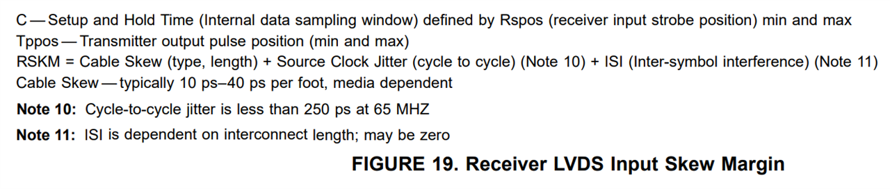
Im using our DS90C382 device in order to convert RGB to LVDS,
Im inserting a clock with reasonable jitter – 200ps but at the output, they are seeing around 600ps of jitter.
Even after improving the input jitter i still see relatively high jitter at the output.
Do you have any idea why this is happening and how we can face this issue?
Thanks!