This thread has been locked.

If you have a related question, please click the "Ask a related question" button in the top right corner. The newly created question will be automatically linked to this question.

TUSB1142: Question to datasheet SLLSFL2A, revised May 2024

Part Number: TUSB1142
Other Parts Discussed in Thread: TPS629206,

Tool/software:

Hi,

We are implementing a USB 3.2 GEN2x1 mux/re-driver with TUSB1142. After reading the datasheet, the following is not quite clear to me:

5.3 Recommended Operating Conditions: "V(PSN) Supply Noise on VCC pins (less than 4MHz) <50mVpp"
- Does that mean 50mVpp are allowed in the frequency range below 4MHz? If yes, which ripple voltage is allowed above 4MHz? Do you have any PSRR values for TUSB1142?
  (The goal is to decide if a TPS629206 based dc/dc-converter is practical or if we need a LDO (not favoured).)

The datasheet says on the first page "Advanced USB power management – Active: 550mW (typical)" and in chapter "5.5 Power Supply Characteristics" PACTIVE-USB-1Port = 275 mW (typical)
- In which case does TUSB1142 draw 550mW (typical)? (I assume that driver and receiver for the not selected lane will be switched off)
- What is the maximum supply current? (to design the power supply)

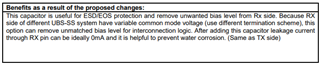
8.2.1 Design Requirements, Figure 8-1 / Table 8-1
- In which cases are the optional AC-coupling capacitors recommended?
(I have seen 7268.USB 3.1 ECN Rx AC Coupling Capacitor Option.pdf in another forum post but that does not a clue why to add AC-coupling capacitors or why better not)

Thanks, Michael

  • Hi Michael,

    Does that mean 50mVpp are allowed in the frequency range below 4MHz?

    Yes this is correct. Above 4MHz I recommend keeping the same amount of noise on the supply (<50mVpp). You can use de-coupling capacitors to help mitigate power supply noise near the VCC pins. We typically suggest using one 0.1uF capacitor to GND near each VCC pin and a 1uF capacitor to GND near the device to handle high-frequency noise. For low frequency noise, you can add a larger, 10uF capacitor near your supply.

    In which case does TUSB1142 draw 550mW (typical)?

    I believe this is a typo in the datasheet. The TUSB1142 can only operate in single port mode, where the active power draw is expected around 275mW. 550mW would be for a dual port application, which this part does not support.

     In which cases are the optional AC-coupling capacitors recommended?

    The optional RX capacitors help protect the RX pins on our device from ESD strikes and get rid of any unwanted common mode bias on the RX lines. You can see the reasoning in that ECN:

    Best,

    Shane

  • Hi Shane

    Thank you for the answers, this clarifies a lot.

    But there is still a concern regarding the power supply. Up to which frequency does TUSB1142 draw current (when driving data lines at 10Gbps)?
    I can use 0201 size 100nF capacitors, place them right next to TUSB1142's power pins and connect them with vias-in-pad to the power and plane. But nevertheless, their usefulness will be limited up to some 100MHz. The PCB will be small and therefore the help of the plane-capacitor limited. 

    What about the frequency range above some 100MHz up to 10GHz? Is this a concern at all? If yes, are there recommendations regarding the decoupling systems maximum impedance in this range?

    Thanks, Michael

  • Hi Michael,

    Up to which frequency does TUSB1142 draw current

    The 1142 will draw current with some noise at any frequency. The key is to keep your noise under the 50mVpp threshold.

    What about the frequency range above some 100MHz up to 10GHz? Is this a concern at all?

    If the voltage ripple is above 50mVpp, then yes this is a concern.

    If yes, are there recommendations regarding the decoupling systems maximum impedance in this range?

    We do not have recommendations for maximum impedance on this. Like I said, we typically recommend adding 0.1uF and 1uF capacitors to GND for mitigating voltage ripple near the device. If you are concerned about higher frequency noise, you can add even smaller capacitors (0.01uF) as well. These would be best to place near the device.

    If you're supply is noisy at 5 - 10GHz frequencies, make sure to isolate the SuperSpeed lines on your PCB so there is no interference. Placing GND planes between your power lines and the signal lines is a good way to do this.

    Best,

    Shane

  • Thank you for the answer

    To clarify: our supply is not noisy at 5 - 10GHz, but it certainly can't deliver current in this frequency range. 

    I will adhere to the reference design TUSB1142EVM. Unfortunately, I could not find a BoM (there is only this slightly blurred schematic diagram in the TUSB1142 EVM User's Guide).
    - Which type of capacitors (manufacturer part number) has ben used? For power supply decoupling and also in the signal line?
    - Which layer stack has been used?
    - And has ripple measurements been done on the EVM?

    Thanks, Michael

  • Michael

    For the 10uF capacitor, we are using GRM188R61C106MA73D and for 0.1uF, we are using GRM155R71E104KE14D.

    The EVM design is a 6 layer board with ground plane adjacent to the power plane to provide additional low frequency power supply noise filtering. But we have not done the power supply ripple measurement on the EVM yet.

    Thanks

    David