This thread has been locked.

If you have a related question, please click the "Ask a related question" button in the top right corner. The newly created question will be automatically linked to this question.

DS280DF810: How to adjust CDR bandwidth and charge pump or set vga and DC gain when cdr loss of lock

Part Number: DS280DF810

Tool/software:

Hi Team,

   There's new design for 25GE application ,based on ds280df810 like below.


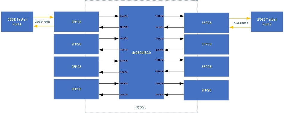
   We found one direction of CDR loss of lock from RX0P/N to TX0P/N when plugging specific 25GE SFP28 module. 0x2f of ds280df810 was 0x50(default) and we also  tried manual data rate configuration and other modes like Midplane/Back plane , Front port egress etc, it's still loss of lock(0x78 =0x20) but signal detect was ok. At the same time the value of 0x02[0] varied from to 0 to 1 continually. Is it possible to adjust CDR bandwidth and charge pump and set CDR or vga gain to solve it ? How to do it?Thanks!

Regards

Richard


  • Hi Richard,

    Were any other bits getting set in Ch registers 0x02?

    Also, is it possible to capture the output of this optical module on a scope?  Typically, we do not see 0x02[0] set when data rate is correct.

    I have a couple questions and debug recommendations:

    1. Can you provide insertion loss estimated for the connections in your block diagram?
    2. If insertion loss is low, let's say <5 dB, can you try manually setting CTLE to index 0?  You can do this by setting adapt mode 0 and following the instructions in the programming guide in section "7.20 Set CTLE Boost Value".
    3. You can adjust the CDR bandwidth by following section "7.31 Adjust CDR Bandwidth and Charge Pump" in the programming guide.  If you suspect that the optical module output has too much jitter for the DS280DF810 to get CDR lock, a higher CDR bandwidth could help with this.
    4. VGA gain can be adjusted by following section "7.32 Set Variable Gain Amplifier (VGA) and CTLE DC Gain Mode" of the programming guide.  You can set this based on the expected electrical output from your optical module.  Getting a scope capture of the optical module output would be helpful with this to confirm that the output appears as expected.

    Thanks,
    Drew