


Part Numbers: TCA9517A, TCA9517, TCA9509
FAQ: Logic and Voltage Translation > IxC >> What is the "VILC" Electrical Spec in I2C Buffers?
VILC = Input LOW Contention Voltage
VILC is the internal voltage value (generally specified in the device datasheet) that is used by the internal logic circuit of the buffer to propagate a LOW signal through the device during a contention situation.
VILC specification as listed in the TCA9517A datasheet:
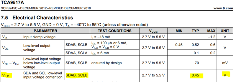
For TCA9517A, its VILC = 0.45V typical. This means to pass a LOW logic signal from B-side to A-side of the buffer, the input voltage needs to be at or below 0.45V for VILB = VILC.
This is different from the I2C specification where VIL = 30% of VCC. In the case of the TCA9517A, VILB = 30% of VCCB.
The reason for VILC is due to bi-directionality of the buffer. The I2C buffer needs a way to re-drive I2C signals in a bi-directional manner without the buffer locking up from re-driving its output back to the input (i.e. drive A-to-B, then the B output drives back from B-to-A).
Therefore, the I2C buffer with static voltage offsets produces a "buffered LOW" (VOLB = 0.52V) as a voltage higher than the VILC in an attempt to avoid re-driving back to the input since the input voltage is lower... VILC = 0.45V.
For more information on what a "buffered LOW" is, please see this FAQ.
For more general information about buffers. Please see this application note: Why, When, and how to use I2C Buffers