


Part Number: DP83867IS
Tool/software:
Hi,
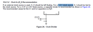
In our current design we changed the VDDIO from 1.8V to 2.5V, RGMII and IO levels are changed to 2.5V with respect to MAC interface. X_I clock input is referenced to VDDIO or 1.8V Clock source.
Thanks
Kevin
Part Number: DP83867IS
Tool/software:
Hi,
In our current design we changed the VDDIO from 1.8V to 2.5V, RGMII and IO levels are changed to 2.5V with respect to MAC interface. X_I clock input is referenced to VDDIO or 1.8V Clock source.
Thanks
Kevin
