Part Number: UCC28C45
Tool/software:
Dear Expert
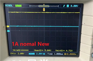
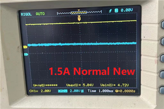
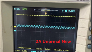
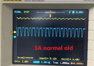
We found different batch UCC28C45 could have under different output current conditions, the output voltage will drop.

Below is our sch ,could u give us some suggstion to find what the reason.
Original question:

Part Number: UCC28C45
Tool/software:
Dear Expert
We found different batch UCC28C45 could have under different output current conditions, the output voltage will drop.
Below is our sch ,could u give us some suggstion to find what the reason.


 \
\