FAQ: Logic and Voltage Translation > IxC >> What Connections of I2C Buffers are not Allowed?
Part Numbers: TCA9517, TCA9517A, TCA9509, TCA9617B, TCA980x, TCA9511A, TCA4307
I2C buffers are often connected in the wrong orientation. This FAQ will provide resources to solve any incorrect connection scheme when using I2C buffers.
TCA9517, TCA9517A, TCA9509, TCA9617B: Buffers w/ Static Voltage Offset
These 4 devices use what is known as a static voltage offset. To learn more about what a static voltage offset is, please see this FAQ.
There are a couple of application notes already out that help to define the correct connection scheme for buffers that have static voltage offset (SVO):
Section 2.4.1. Why, When, and How to use I2C Buffers
Resolving Improper Implementation of the Static Voltage Offset on I2C Buffers
In short, two SVO's cannot connect on the same node. If we are examining TCA9617B for example, the B-side to B-side connection is not allowed.
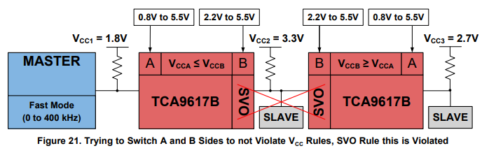
A-to-B is okay
B-to-A is okay
A-to-A is okay
B-to-B is not allowed
***Note, SVO's are not always on B-side of every I2C buffer. For example, the TCA9509 actually switches the offset side to the A-side. This means for TCA9509, A-to-A connection is not allowed.
TCA980x: Current Mirror
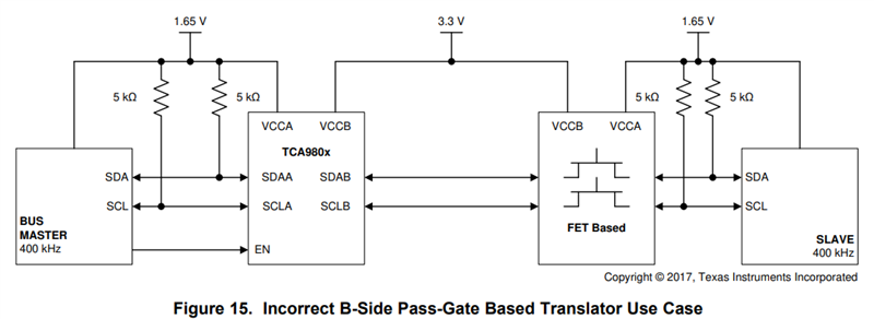
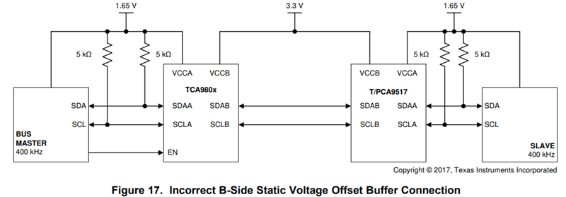
TCA980x which includes TCA9800 / TCA9801 / TCA9802 / TCA9803 use what is known as a current mirror for direction control on the B-side. This device has an internal current source that is sensitive to other current sources such as pull-up resistors or leaky ESD cells.
In the same manner as SVO's, the B-side of the TCA980x cannot be connected to another TCA980x B-side or a SVO from another buffer.
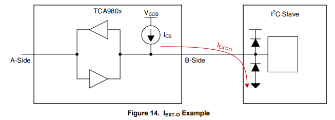
TCA980x must also adhere to the I-EXT-I and I-EXT-O specifications listed in the datasheet. Otherwise, the internal current source (ICS) may struggle to determine which side of the buffer is being pulled LOW which means the device has a hard time propagating a LOW through the buffer.
I-EXT-I:
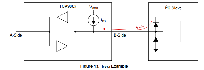
I-EXT-O:

Incorrect Connection Examples from the Datasheet:
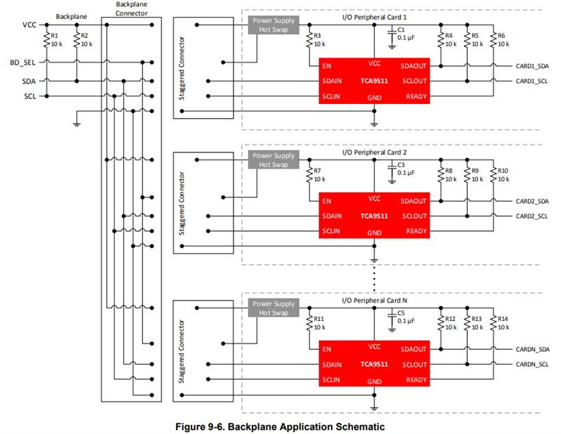
TCA9511A, TCA4307: Hot-swap Buffers with Dynamic Offset
TCA9511A and TCA4307 are hot-swap I2C buffers both with dynamic offset.
*Note the two devices are p2p compatible with each other. The only difference between these devices is that TCA4307 implements a "stuck bus recovery" feature.
TCA9511A and TCA4307 are unique devices as they are capable of detecting a stop condition or idle condition on the "IN" side of the buffer. The "IN" side of the buffer is denoted as SCLIN & SDAIN.
In a non-hot swap applications, the TCA9511A and TCA4307 can be connected in series as long as the VIL is met for every I2C device on the bus. TCA9511A and TCA4307 implement a dynamic offset voltage that adds a VOS offset voltage to the VOL for every buffer in series. See the description for "Dynamic Offset" in the [FAQ] What are the different I2C Buffer Direction Control Mechanisms?
Incorrect connections for hot-swap buffers would include having the "OUT" side face the powered backplane. This defeats the purpose of the hot-swap buffer being able to detect stop or idle conditions on the backplane side of communication.
In hot-swap applications, the engineer should follow this connection scheme where the "IN" side faces the backplane. This assumes that the CARD power is off, and the backplane is already powered, possibly running I2C transactions on the bus.