This thread has been locked.

If you have a related question, please click the "Ask a related question" button in the top right corner. The newly created question will be automatically linked to this question.

AM26LS32AC: The schematic review for the AM26LS32AC

Part Number: AM26LS32AC

Tool/software:

Hi,

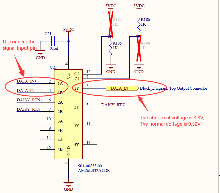
We use the AM26LS32AC for the LED control signal, and now, there are more than 10% AM26LS32AC has below issue, please kindly review the schematic

and advise why we have the below issue(The 1Y output voltage is 3.8V and the normal voltage is 0.52V), and it there any improve to avoid this issue, thanks.
 

  • What exactly do you mean with "disconnect"? Is there a termination resistor, and is it still connected?

  • Hi Zhang,

    Can you verify what is connected to the DATA+IN net? 3.8V is not the expected high logic for the device. 0.5V is also a bit high for a logic low for the device.

    As Clemens pointed out, are you using termination on the RS422/485 side (A and B pins)?

    I'm also assuming you are saying that when you disconnect the cable, you expect 1Y to be a logic high? But you are not seeing this? The device itself doesn't have internal fail safe biasing, the Vth+ for the device is 200mV so you may need to add an external fail safe to ensure the voltage is what it should be when it's disconnected.

    -Bobby

  • Hi Clemens/ Bobby,

    Thanks for your kindly reply.

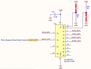
    Please refer to below schematic:

    The Signal DATA_RTN+ and DATA_RTN- from AM32LS31CDR:

    we have the 100ohm termination resistor between the DATA_IN+ and DATA_IN-:

    We have the 2Kohm resistor between the LED and DATA_IN and series connect 51ohm resisor on LED and DATA_IN circuit for our output connector:

    So please review our design and advise if there is any error or risk to cause the AM26LS32AC failure?


    3.8V is not the expected high logic for the device. 0.5V is also a bit high for a logic low for the device.

    Our normal board is 0.56V DATA_IN when we the power on that it is less than 0.8V, so please advise why the 0.5V is also a bit high for a logic low

    I'm also assuming you are saying that when you disconnect the cable, you expect 1Y to be a logic high? But you are not seeing this? The device itself doesn't have internal fail safe biasing, the Vth+ for the device is 200mV so you may need to add an external fail safe to ensure the voltage is what it should be when it's disconnected.

    Please advise how to add an external fail safe and how to test this right voltage, thanks.

  • Our normal board is 0.56V DATA_IN when we the power on that it is less than 0.8V, so please advise why the 0.5V is also a bit high for a logic low

    Are you actually measuring 0.5V from the Y pin? Normally when there is no load (or very low loading) the VoL of a FET will be closer to GND. At 0.5V it probably means there's several mA of current being drawn. 

    If I'm understanding correctly (The 1Y pin goes to a 2k resistor into an LED), you are toggling on an LED when the signal goes low so there is going to be a larger load than in normal situations. So this would make sense why your output is higher than ~0.1V.

    Please advise how to add an external fail safe and how to test this right voltage, thanks.

    Just add a pull up resistor on 1A and a pull down resistor on 1B of U21. When the cable isn't connected, it should force the 1Y pin to be a logic high output. If you put a pull up resistor on 1B and a pull down resistor on 1A of U21 then when the cable isn't connected you can force the 1Y pin to be a logic output low. It depends what you want the logic to be. Make the pull up resistor be about 1k ohms and the pull down resistor to be about 1k ohms. 

    That should allow you to set the '1Y output of U21 when disconnected'  to whatever state you need it to be. Otherwise it will float and pick up noise and become a random output. This device doesn't have a internal fail safe to ensure a logic level when disconnected so you need to add an external fail safe circuit (pull up and pull down resistors on the differential inputs).

    -Bobby

  • Hi Bob,

    Thanks for your reply.

    Are you actually measuring 0.5V from the Y pin? Normally when there is no load (or very low loading) the VoL of a FET will be closer to GND. At 0.5V it probably means there's several mA of current being drawn. 

    If I'm understanding correctly (The 1Y pin goes to a 2k resistor into an LED), you are toggling on an LED when the signal goes low so there is going to be a larger load than in normal situations. So this would make sense why your output is higher than ~0.1V.

    You are right, this is the LED control design;

    Just add a pull up resistor on 1A and a pull down resistor on 1B of U21. When the cable isn't connected, it should force the 1Y pin to be a logic high output. If you put a pull up resistor on 1B and a pull down resistor on 1A of U21 then when the cable isn't connected you can force the 1Y pin to be a logic output low. It depends what you want the logic to be. Make the pull up resistor be about 1k ohms and the pull down resistor to be about 1k ohms. 

    That should allow you to set the '1Y output of U21 when disconnected'  to whatever state you need it to be. Otherwise it will float and pick up noise and become a random output. This device doesn't have a internal fail safe to ensure a logic level when disconnected so you need to add an external fail safe circuit (pull up and pull down resistors on the differential inputs).

    This is very detail test process, I will test base on your comment;

    What exactly do you mean with "disconnect"? Is there a termination resistor, and is it still connected?

    Sorry for my wrong description,the "disconnect" is mean we have no differential signal input; And the 1Y voltage is 3.8V;

    BTW, let us back to my initial question, sorry we have 10% abnormal chip because we conducted a replacement test,

    and the failure phenomenon is followed the chip, we close the so we consider if there are any error or risk for our schematic diagram,

    so please also review our schematic diagram again, and advise if we need to add any protection device to avoid the failure situation, thanks.

  • Hi Bob,

    We add the 1Kohm push up to 1A and 1Kohm push down 1B and the problem is solved, so many thanks for your and Clemens' support;

    Now we have a suspicion that the voltage state as below screenshot, so the output voltage is indefinited;

    We will update the program to add the logic status refresh to make sure the output voltage logic to low and will feedback to you the result soon, thanks.

  • Yes; with the termination resistor present, no signal means that the differential input voltage is 0 V.

  • We add the 1Kohm push up to 1A and 1Kohm push down 1B and the problem is solved, so many thanks for your and Clemens' support;

    Now we have a suspicion that the voltage state as below screenshot, so the output voltage is indefinited;

    We will update the program to add the logic status refresh to make sure the output voltage logic to low and will feedback to you the result soon,

    Thanks for getting back to us and verifying. 

    Yes, when you disconnect from a driver, there is no differential voltage seen from the device's input pins so you are likely in between the Vth- and Vth+ which is causing an undetermined voltage. The 10% failure rate is likely due to some bias current (silicon doping differences) between parts. 

    You can fix this by either adding the external resistors or by using a device with a Vth+ in the negative value range (this is what we call a device with internal fail safe protection). 

    -Bobby