This thread has been locked.

If you have a related question, please click the "Ask a related question" button in the top right corner. The newly created question will be automatically linked to this question.

TUSB211A: TUSB211A

Part Number: TUSB211A

Tool/software:

Hi,

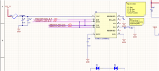
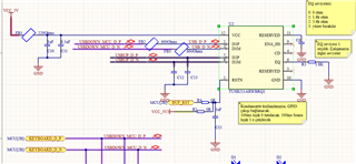
I am currently using TUSB211A in my design. My schematic as shown as below. 

when ı run my hardware usb data signals does not working. Can you review and feedback me for this issue. 

  • Hi Recep,

    I see a few things in this schematic that may be causing errors.

    First, I see that the D1P/M and D2P/M have different names. These should have the same net names, as these lines on the layout are meant to connect underneath the device. Because of the different net names, I'm lead to believe they are disconnected under the device, thus why the USB data lanes would not be working.

    Next on the USB2 data lanes, I see D1P/M are connected to what I believe are common-mode chokes. These can degrade the signal integrity, so unless there is a large amount of noise in the signal, we recommend against these.

    On the D2P/M lines, I see two capacitors pulling down on the on the data lanes. What are these for? They are likely degrading the signal quality a great deal.

    Finally, I see you have the RSTN pin divided between an input signal, a pull-up, and a capacitor connecting to ground. Please make sure this setup properly allows the redriver to be enabled when needed. Additionally, please ensure that the power-up timing requirements are not being violated, and that the redriver is enabled before data is sent through the redriver.

    Thanks,

    Ryan

  • Hy Ryan,

    First of all ,I have chosen this IC so that I can use about 7 m usb cable in my system. Do you think this is the right choice?

    Thank you for quick response. I updated my design as you said.Can you review and give a feeadback me again. Thank you su much.

  • Hi Recep,

    For a 7M cable length system, I would recommend increasing the settings on the redriver, potentially all the way up to Boost 3 and RX_SEN high. Our redrivers are typically spec'd for a max of 5 meters when used with a pre-channel length of 5 meters when using the highest settings. At longer than 5 meters, we can't guarantee that the signal will be strong enough. In the case that just this redriver is not enough to boost the signal as needed, you can add another redriver in the system, as these redrivers can be daisy-chained for improved overall performance.

    e2e.ti.com/.../faq-tusb216i-how-do-you-create-a-system-with-a-10-meter-passive-cable-using-a-usb2-redriver

    For the new schematic sent over, this looks improved over the previous one. For boost 3, R3 can be left floating.

    One change would be to change C15, the cap pulling RSTN down, to 100nF, per the typical application.

    Please let me know if you have any other questions.

    Thanks,

    Ryan

  • Hi Ryan,
    I rework my PCB what you recomended. I demontage all ferrite and capacitor on data signals. And ı use jumper cable for data signal shortin as show as image which i send. But my current PCB deisgn still not working. 

  • Hi Recep,

    Reworking the PCB as you have with wires could also degrade signal quality.  I believe Ryan was expecting you to refab the PCB board to conform to the TUSB211A datasheet layout instead of use jumper wires.  Is this possible for you to do?

    Can you let me know in detail what is not working properly?  What is your test procedure and pass/fail criteria?  Have you made any measurements on the USB DP/DM lines with an oscilloscope or protocol analyzer that you can share?

    Thanks,

    Nicholaus

  • Recap,

    In addition to the comments from Nicholaus, are you testing with a short cable(1-3m instead of 7m) to verify functionality?

  • Hi Recep,

    I agree with Undrea that a short cable should be tested as well.  Any update on this issue?

    Thanks,

    Nicholaus

  • Closing due to inactivity.

    Regards,

    Nicholaus