This thread has been locked.

If you have a related question, please click the "Ask a related question" button in the top right corner. The newly created question will be automatically linked to this question.

THVD2412: THVD2412 Technical Query regd connections

Part Number: THVD2412
Other Parts Discussed in Thread: RS485FLDPLXDRCEVM

Tool/software:

Hi Team,

We are using RS485 transceiver IC in our design, we have bought the evaluation board - RS485FLDPLXDRCEVM (with transceiver IC: THVD2412 mounted in it).

, in which when we tried to interface with a slave device, when we connect TX+ with RX- and connect TX- with RX+ , Its working, but as per RS-485 protocol this is wrong. Can you clarify why this is functioning like this?.

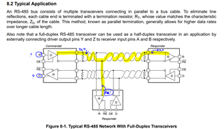
In the transceiver datasheet also, its provided master slave connection as contradictory, please refer below image:

TX+ of master -> connected to RX+ of one responder and RX- of another responder, How, please clarify??

and the Transmitter (Driver pin) is named as R?

Receiver is named as D?

Can you clarify is there any issues in datasheet image?

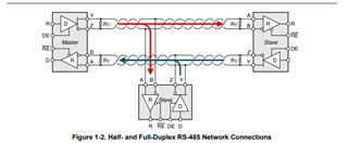
As per protocol, we need to connect:

TX+ of master -> RX+ of slave

TX- of master -> RX- of slave

RX+ of master -> TX+ of slave

RX- of master -> TX- of slave

Refer the images below:

Kindly clarify on the correct connection for transceiver IC: THVD2412, we are in testing phase, hence waiting for your quick and valuable feedback.

Thanks,

Arunasri, 

Sanmina

  • TX+ with RX- and connect TX- with RX+

    TX+ of master -> connected to RX- of slave

    TX- of master -> connected to RX+ of slave

    On this configuration only its working, Kindly clarify..

  • That datasheet image (figure 8-1) indeed is wrong; the names of the R and D pins are exchanged.

    On the EVM and in the datasheet, the bus pins are named A/B/Y/Z. I do not know how you assign those TX+/TX−/RX+/RX− names, but note that just because the letters "A" and "B" appear does not necessarily mean that they have the same meaning. For the THVD2412 (and all other TI transceivers, and most transceivers by other manufactuers), A = RX+, B = RX−, Y = TX+, Z = TX−.

  • We have also assumed the same: A = RX+, B = RX−, Y = TX+, Z = TX−

    While considering the same, the communication between the transceiver and slave(responder) is happening when we connect :

    Y (TX+) -> connected to RX- of slave 

    and

    Z (TX-) -> connected to RX+ of slave

    We have double checked the responder datasheet and we suspect that there might be some issue in evaluation board - RS485FLDPLXDRCEVM (with transceiver IC: THVD2412), can you please check further and let us know


  • As far as I can see, the labels on the EVM are correct.

    Please check that when the D input is high, the Y output is high and the Z output is low.
    Also check that when the A input is higher than B, the R output is high.

  • and the Transmitter (Driver pin) is named as R?

    Receiver is named as D?

    This looks like an error/typo. 

    TX+ of master -> connected to RX+ of one responder and RX- of another responder, How, please clarify??

    If the differential outputs are connected incorrectly then the logic on the Routput would be flipped (opposite) of the D input. 

    In most systems you would want (I'm going to use the THVD2412's pinout to explain), the Y pin to connect to the A pin and the Z pin to connect to the B pin. I think from your naming convention it should be Tx+ to RX+ and TX- to RX-. Doing this should allow for the Routput pin of the receiver to have the same logic as the Din pin of the transmitter. 

    We have double checked the responder datasheet and we suspect that there might be some issue in evaluation board - RS485FLDPLXDRCEVM (with transceiver IC: THVD2412), can you please check further and let us know

    Figure 3-3 of the EVM user's guide shows the routing. From what I can see, it looks like the labels on the EVM are correct and the pinout matches the labels.

    If you suspect the EVM is incorrect, you could do a loopback test where you short the Y pin to A and the B pin to Z and monitor D and R to see if they follow each other. If D is low R should be low, if D is high then R should be high. If it's reverse/opposite then something is wrong. 

    -Bobby