This thread has been locked.

If you have a related question, please click the "Ask a related question" button in the top right corner. The newly created question will be automatically linked to this question.

TFP401A: Strange Line appears at the boundary of pixel value

Part Number: TFP401A
Other Parts Discussed in Thread: TFP401

Tool/software:

Dear, Support Team.

We are currently using the TFP401APZP chip for a 480x480 resolution, 18-bit color depth display.

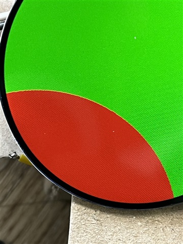
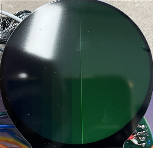
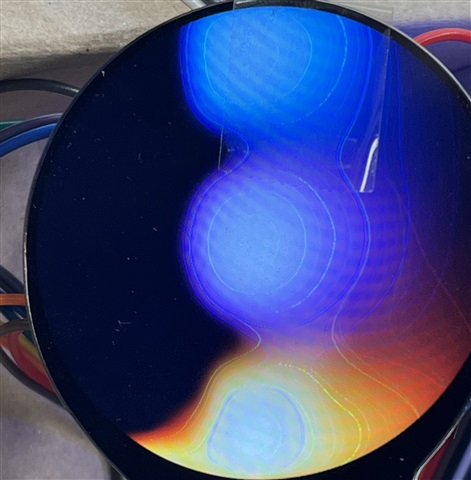
We are encountering an unusual issue where a distinct line appears along the horizontal boundaries of color values.
This line disappears along the vertical axis.
Notably, this is not a case of color banding.


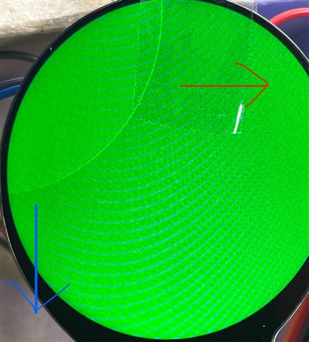
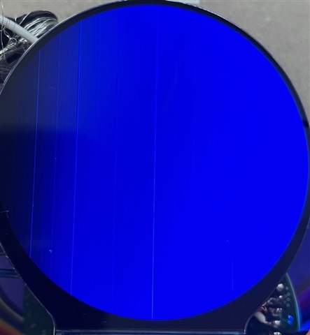
The below shader is used to generate a green gradient image above, where the minimum color width is expected to be 32 pixels.
However, the issue presents with a 1-pixel line that appears contrary to this expectation.

// GLSL

void main()
{
    vec2 coord = gl_FragCoord.xy;

    ivec3 ic = ivec3(0, int(coord.x) / 32, 0);

    if (ic.y > 7) 
    {
       ic.y = 8;
    }
    
    fragColor = vec4(vec3(ic) / 255.0, 1.0); 
}


Configuration:

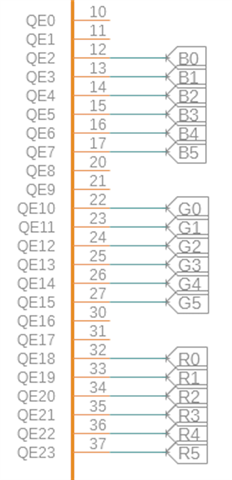
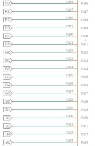
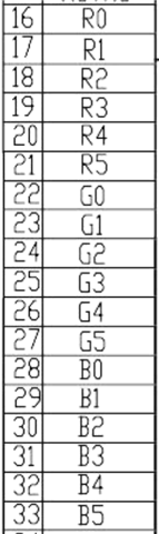
Raspberry Pi 4 HDMI -> TFP401 -> (Drop 2LSB) -> Display driver(ST7701SN)

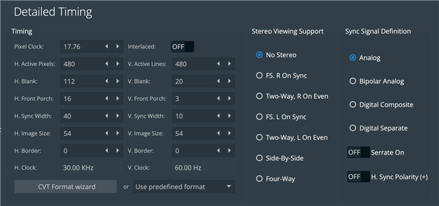
Below is Display Timing info used for HDMI.


The display works correctly when directly interfaced with an ESP32 using an 18-bit RGB configuration.
We have reviewed our hardware setup and found no apparent issues


We welcome any advice or suggestions you might have.

Best regards,

Gunwoo Ahn

  • Hey Gunwoo,

    Does this issue occur across multiple boards/ devices? 

    How have you confirmed its not a color banding issue?

    These line may be due to the fact that the LSB is being dropped rather than the MSB. Is the signal being sent a nd process a big-endian or little-endian signal? This may be swapped between the RPI and the ESP32.

    Best,

    Vishesh Pithadiya

  • Hi Vishesh Pithadiya,

    This issue persists across different combinations of Raspberry Pi and display setups.(had only one TFP401 board)

    I have confirmed that this is not a case of color banding because the image is correctly quantized at 2-LSB when displaying a 0-255 level gradient, with pixel-perfect matching (result, each set of four pixels shares the same brightness).

    I believe neither MSB nor LSB settings are at fault. If there were a mismatch in the endian configuration, the entire image would appear incorrect.

    Interestingly, the image is perfect.
    Except for a corrupted single pixel at the boundary of the gradient value,
    despite the minimum width being 4 pixels.
    I attempted to reproduce this issue using color bit scrambling on https://www.shadertoy.com/ but failed.

    Best regards,

    Gunwoo Ahn

  • Hey Gunwoo,

    In the case where the image is perfect, and issues only stem at the gradient this is not a hardware issue, it stems from the removed LSB values.

    The edges of the gradient value will be most affected by the 24 -18 bpp pixel conversion, as in this transitionary range is where the extra bits are used the most. 


    The display works correctly when directly interfaced with an ESP32 using an 18-bit RGB configuration.
    We have reviewed our hardware setup and found no apparent issues

    The fact that when using an 18bpp video signal to start doesn't result in such glitching also affirms this theory.

  • I agree that the core of the issue likely stems from the 24 to 18 bpp conversion.

    However, I don't believe the conversion itself is the direct cause, considering the axis dependency of the issue, as previously described. To aid in our analysis, I've attached the brief schematic for the TFP401 to display connection.

    In my view, the axis dependency might be related to the display's timing, which processes rows first. Could there be a possibility that bit corruption occurs during this phase?

  • Hey Gunwoo,

    Are you able to share the entire schematic?

    Additionally what is the pin-strap setup you are using?

    what is the status of the PIXS and ~STAG?

  • Apologies for the delayed response.

    Currently, sharing the entire schematic poses some difficulties.

    However, I've attached the specific schematic section for the PIXS and ~STAG.

    Best regards,

    Gunwoo Ahn

  • Hey Gunwoo,

    I am not familiar with the symbols being used. Is PIXS/ ST/ OCK_INV  being pulled up or pull down on the board? 

  • Apologies for the insufficient information.

    These are jumper unit, and currently, all are not connected.
    So, ST is pulled up, PIXS and OCK_INV are pulled down.

    Is this miss configuration?

  • Hey Gunwoo,

    Try the following combinations of these control pins:

    current setup: St  = 1, PIXS = 0, OCK_INV = 0

    1) St  = 0, PIXS = 0, OCK_INV = 0

    2) St  = 0, PIXS = 1, OCK_INV = 0

    3) St  = 0, PIXS = 0, OCK_INV = 1

    4) St  = 0, PIXS = 1, OCK_INV = 1

    5) St  = 1, PIXS = 1, OCK_INV = 0

    6) St  = 1, PIXS = 0, OCK_INV = 1

    7) St  = 1, PIXS = 1, OCK_INV = 1


    The ST pin shouldn't play much of a role, but its good to test.  The polarity of OCK may affect the output due to some duty cycle issues. The STAG pin may also help this case if you are able to test this pin. The STAG pin will stagger the even and odd outputs 

  • Following your suggestions, I tested below combinations. 

    1) St  = 0, PIXS = 0, OCK_INV = 0 → reduced lines, though some remains.
    3) St  = 0, PIXS = 0, OCK_INV = 1 → reduced lines, though some remains. (uncertain)
    5) St  = 1, PIXS = 1, OCK_INV = 0 → resulted in half of the display being broken
    6) St  = 1, PIXS = 0, OCK_INV = 1cleared all lines

    edit) 

    I adopted the configuration St = 1, PIXS = 0, OCK_INV = 1, which resulted in the strange lines at value boundary disappearing.

    However, there is now a slight random noise line appearing vertically.

    What should I investigate to resolve this?

    (STAG pin is high state)

  • I'm not too sure to be honest.

    If its slight random noise, its best to verify that all connections are sound, and the cables used are properly shielded. Are you able to send a picture?

  • This is vertical noise I mentioned, though it's challenging to capture the exact visual as seen by the eye.

    When I revert to the configuration St = 1, PIXS = 0, OCK_INV = 0, the noise disappears.

    Could this be caused by mismatch of OCK_INV and to HDMI timing options ?

  • Potentially, It may be useful to check if ~STAG plays a role in removing the noise.

    This seems to be associated with the polarity of the OCK so I recommend double checking the HSYNC and VSYNC timing and make sire the pixel clock is at the expected frequency

  • Vertical noise issue has been resolved.

    It turned out that related to Ubuntu's DRM software usage.
    Now, the display is perfectly clear.

    I truly appreciate your consistent assistance and effort in helping us troubleshoot and resolve this issue.

    Best regards,

    Gunwoo Ahn

  • No problem!

    Glad we got it working.