A related question is a question created from another question. When the related question is created, it will be automatically linked to the original question.
If you have a related question, please click the "Ask a related question" button in the top right corner. The newly created question will be automatically linked to this question.
Thanks for sharing links. I would like to re-open the post.
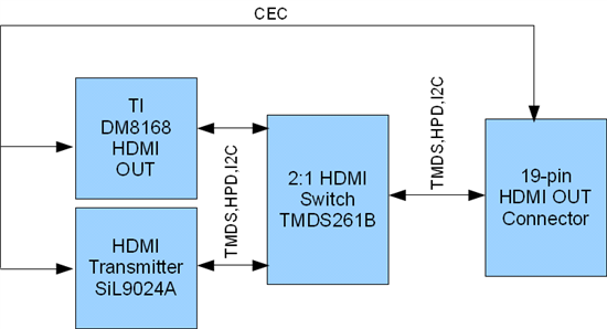
As shown in attached image, we want to switch 2 HDMI devices by TMDS261B. TMDS261B uses only TMDS[1:0],HPD[1:0],I2C[1:0] pins for switching. But it does not has CEC[1:0] pins.
Can we short CEC pins of both HDMI devices and give it to 19-pin HDMI connector (as shown in image)?
CEC, from what I understand, does not need a switch, because all participants are on the exact same bus. So yes, the diagram you have shown should be correct. TI's HDMI switches have nothing to do with the CEC signals.
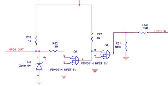
Thanks for the help. As TMDS261B and TMDS361 has internal ESD protection for HPD out, is it necessary to connect FET logic circuit on HPD line (As shown in SN65TMDS361 EVM)?
According to the HDMI interface spec, the standard 3.3V output should be adequate. We have seen issues with some equipment which was the reason for the added circuit. My recomendation would be to have a 5V signal for HPD.
Thanks. As TMDS261B and TMDS361 datasheet mentioned, "They have ESD protection on all input side". So is it necessary to connect ESD protection device on output side??? Note: TMDS361 EVM doesn't contains output ESD protection.
TMDS261 has a fairly high ESD structure internally. Depending on IEC requirements and system implementation, it is possible that this may not be enough. I like to plan for the in-line ESD structure just in case an additional solution is needed. It is only a few discrete components if the ESD structure is not installed, but allows for pop/no-pop option if needed. You should not need an external ESD structure for the output side, unless you are going outside the TMDS261 enclosure.