This thread has been locked.

If you have a related question, please click the "Ask a related question" button in the top right corner. The newly created question will be automatically linked to this question.

TCAN1043-Q1: CANL short to GND

Part Number: TCAN1043-Q1

Tool/software:

Hi TI expert,

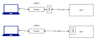
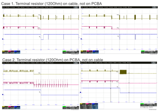
I test with two cases: CAN_H shorted to GND (1) and CAN_L short to GND (2)

For each case I measure the nFAULT pin. For case (1), nFAULT changed state (expected - OK) but for case (2), nFAULT not change (Still High).

Follow the state diagram, I am make sure the IC in Normal state.

In the table 9-1, CANL shorted to GND, nFAULT =Low in normal mode only

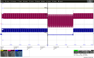
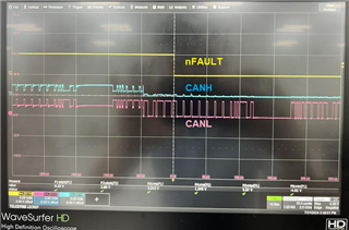
(1) CAN_H short to GND 

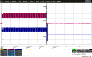
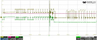
(2) CAN_L short to GND (Pink - C2 is nFault)

Question: 

- Is test case (2) with expect nFAULT=L correct or not

- If correct pleas suggest to fix it.

Thanks.

--Tuong Pham

  • Hi Tuong,

    It looks like the first figure here may be mislabeled. Before the fault is applied the blue signal is switching between 2.5V and ~1.0V which is consistent with CANL behavior and the pink signal switches between 2.5V and 4.0V which looks like CANH behavior. Can you confirm if this is the case? If so it looks like both waveforms show the same CANL short to ground test. 

    What data rate is being run in yours system for this test case? The bus fault detection feature only works reliably for data rates of 400kbps or slower (bit time of tCBF = 2.5us). 
    What are the bus conditions for this test? What are the termination values? What are the characteristics of the signal harness between communicating nodes?

    Regards, 
    Eric Schott

  • Hi Eric,

    The first figure is correct, please note that CAN_L is -5V offset.

    I retest as below, with C1 is nFault, C2 is CAN_H, C3 is CAN_L

    Data rate i believe it's less than 500kbps

    Test conditon: MCU => CAN => Kvaser => Laptop

    Termination Reistor: 120R (60R for each line)

  • Hi Eric, 

    could you please take a look at this issue it’s quite urgent . Thanks

  • Tuong,

    Thanks for your patience, can you try different data rates to see if nFAULT toggles low? I would expect a slower data rate make it work.

    The bus fault detection works by measuring the differential current between CANH and CANL. When the current passes a certain threshold based on the fault type, the nFAULT pin will go low. In this case, since CANL to GND isn't a particularly abnormal condition, while still being considered a fault, the current may not be passing the threshold expected. 

    Is there a CMC on the board? Is it possible to share a schematic?

    Regards,

    Eric Hackett

  • Hi Eric,

    Sorry I was missed this discuss during holiday. 

    Regarding sch, please refer to photo. We do have CMC. 

    Your concern about data rate, I cannot slowdown data rate as it from MCU. 

    I also don't see problem with CANL shorted to GND, but my testing team they expect nFAULT should behaviors similar to CANH.

    Looking for your feedback.

  • CMC should be move to the right of resistor 120 ohm

  • could you please give feedback.

  • Hi Tuong,

    In your schematic, the termination resistors are on the IC-side of the common mode choke. This will allow the initial current from the dominant drive state to appear nominal to the transceiver while the short is isolated from the circuit from the inductance of the CMC. If the dominant period were to last long enough (if the data rate was lower), the circuit would reach a steady state and the transceiver would be able to more reliably detect bus faults. Alternatively if the termination were placed on the bus-side of the CMC, the fault current would be more apparent to the transceiver earlier in the bit time. 

    Is it possible to repeat your testing with the R92/R95 removed and the additional 120-ohms placed elsewhere in the system? 

    Regards, 
    Eric Schott

  • Hi Eric,

    I carried out the test with two cases: case 1 is Terminator res not on DUT and case 2 is 120R on DUT

    And below is result:

    Looking for your feedback.

    Thanks

  • Tuong,

    This test proves Eric Schott's point. Moving the resistance close to the IC for detection allows for the transceiver to more accurately (and quickly) measure the current for bus fault detection. In the PCB case, as soon as the short occurs on CANL, nFAULT goes low when there are four dominant to recessive pulses, and stays low. Whereas with the termination on the cable, nFAULT only goes low when there are several dominant pulses in a row, allow for the current measurement to show a bus fault while dominant, but as soon as the dominant bits stop, the nFAULT pins goes back high because it cannot accurately detect the short during the recessive and dominant timing. 

    Regards,

    Eric Hackett