Tool/software:
The customer found that the screen display was disturbed during EMC RI test. Please refer to the attached video and sch file for details. May I ask what could be the possible cause? Do you have any suggestions for improvement?Thanks.
This thread has been locked.
If you have a related question, please click the "Ask a related question" button in the top right corner. The newly created question will be automatically linked to this question.
Tool/software:
The customer found that the screen display was disturbed during EMC RI test. Please refer to the attached video and sch file for details. May I ask what could be the possible cause? Do you have any suggestions for improvement?Thanks.
Hi Jon,
I will look over the schematic and provide feedback by the end of the week. Can you also provide the following information?
Glenn
Hi Jin,
Do you have a register dump all pages for a good and bad case? -----Do you mean the register data?
Yes, need the register data. This will allow me to see if something is program incorrectly. Please take it when in a good state then in a bad state. Make sure to get all the pages.
Glenn
Glenn,
Now the customer has found that there is a problem over 800M when doing EMC RI test. Then customer carefully examined this circuit with a serial rate of 2G, and now the camera is 720P@30 The 934 is configured with a 10 bit working mode, so the serial rate is approximately 500Mbps. In that case, will the POC circuit still use this one?
Hi Jon,
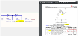
Looking at the PoC used, 2G PoC network from our data sheet was used, but they modified L2. It was changed from the 4.7uH inductor in the datasheet to the 22uH one here instead.
Why was this changed? Due to the PoC not being exactly what is recommended, would suggest to reach out to the vendor of the PoC. They can help you with your request. Since there was a change on the PoC, where simulations completed on this PoC network to determine if the high-speed channel to still meet our channel specs?

Glenn
Glenn,
The register data is list:
/* digital reset0, digital reset1 */
{0x4c, 0x01},//
/* RX CRC check, i2c passthrough */
{0x58, 0x58},
/* DES Device ID ds90ub948q*/
{0x5c, 0xb0},
/*slave ID mxt1664*/
{0x5d, 0xd8},
{0x5e, 0x3a},
{0x65, 0xda},
/* GPIO0 for mxt1664 irq - Remote-default mode */
{0x6d, 0x7e},
Looking at the PoC used, 2G PoC network from our data sheet was used, but they modified L2. It was changed from the 4.7uH inductor in the datasheet to the 22uH one here instead.--------POC circuit recommendation 4.7u-22uH. Customer used 22uH, do customer need to change it to 4.7uH?
Hello Jon,
The team is currently out of office due to the US public holiday and will resume activity on 9/3. Thank you for your patience during this time
Best Regards,
Casey
Jon,
POC circuit recommendation 4.7u-22uH. Customer used 22uH, do customer need to change it to 4.7uH?
This should work as well, but customer still need to test the channel to make sure it meets datasheet specs.
Glenn