This thread has been locked.

If you have a related question, please click the "Ask a related question" button in the top right corner. The newly created question will be automatically linked to this question.

SN65HVD1477: SN65HVD1477DGKR

Part Number: SN65HVD1477
Other Parts Discussed in Thread: AM6422,

Tool/software:

Hi,

We would like to use RS-485 transceiver, SN65HVD1477DGKR along with a microprocessor (similar to TI's AM6422) to implement full-duplex transceiver in one of our products.

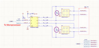
Could you please review the schematics of the RS-485 shown below?
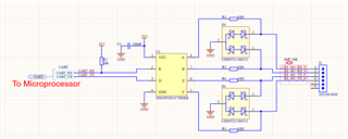
Could you pleas confirm the 30 ohm differential impedance?

Thank you.

Regards,

Kavin

  • Hello Kavin,


    • Is this SN65HVD1477 part a middle or end node for the system?
    • What type of protection and to what levels are you aiming to provide for the SN65HVD1477?
    • Are your 10 Ohm resistors pulse proof?


    In regard to the 30 Ohm differential impedance, where is this located on the schematic? I am not directly seeing the resistor placement.


    Best,

    Ethan

  • Hi Ethan,

    The SN65HVD1477 part is an end node that will be connected to another development board for communication, which also has an RS-485 interface. We will be using RS-485 for serial port communication as well.

    The UART_RX and UART_TX signals of the microprocessor are 3.3V signals, so we didn't use any level shifter for those signals. These signals are directly connected to the microprocessor. The 3.3V power supply to the VCC of the SN65HVD1477 comes from a buck converter and is already filtered. We used TVS diodes at pins A, B, and Y, Z as shown in the schematic. Is this sufficient? We expect that the other development board with the RS-485 interface will also have 3.3V signals.

    Would you please recommend a level shifter in case the RS-485 signal is 5V from the other board? Do we need additional protection for communication between the boards?

    Please note that the connector 205338-0006 is the GPIO, and pins 5 and 6 of the GPIO will be connected to power and GND to power the whole system.  

    Yes, the 10 Ohm resistors, CRCW040210R0JNEDHP (5%, 0402, 0.2W), are pulse-proof.

    Thank you for your support.

    Regards,

    Kavin

  • Hi Ethan,

    My apologies, I missed this question.

    ++++++++++++++++++++++++++++++++++++++++++++++++++++++++++++++++++++++++++++++++++++++++++++++++++++++++

    Regarding the 30 Ohm differential impedance, where is this located on the schematic? I do not see the resistor placement directly.

    ++++++++++++++++++++++++++++++++++++++++++++++++++++++++++++++++++++++++++++++++++++++++++++++++++++++++

    I did not use a 30-Ohm resistor. I am asking if it is sufficient to maintain a 30 Ohm (target impedance) for the differential pairs A, B and Y, Z during PCB design, or should I route it as single-ended signals?

    Thank you.

    Regards,

    Kavin

  • Kavin,


    Thank you for your response. Those TVS diodes should be sufficient.

    For the level shifter, if one RS-485 device is powered by 3.3V and the other is powered by 5V, then a level shifter is not needed for the differential lines.


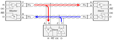
    Because RS-485 is a differential signal, it is recommended that termination resistors match the characteristic impedance to avoid reflections on the line. Typically, this would be 120 Ohm resistor placed on the end nodes. Reference R_T in the image below:

    For more information on termination, please reference the termination section of this document.


    Best,

    Ethan

  • Hi Ethan,

    Thank you for your prompt response.

    Please find attached the schematics. As recommended in the document, I have placed 120 Ohm (0201,1%, 1/20W) termination resistors between the differential pairs. I have also changed the characteristic impedance of the differential pairs to 120 ohms.

    Could you please let me know if the 0201-termination resistor is sufficient?

    Thank you.

    Regard,

    Kavin

  • Kavin,

    That resistor is not sufficient. A 1/4 W rating is suggested, but 1/8 W at minimum could also work. Other than that, your schematic looks good. 

    Best,

    Ethan