This thread has been locked.

If you have a related question, please click the "Ask a related question" button in the top right corner. The newly created question will be automatically linked to this question.

TCAN1043-Q1: Application Questions

Part Number: TCAN1043-Q1

Tool/software:

Hello team,

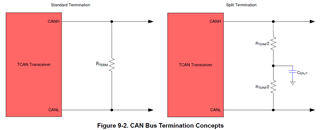
1. The CAN datasheet recommended using a 120Ω resistor for the terminal node, but in real case, non-terminal nodes may use R1=R2=1.3KΩ as the terminal resistor.
a) What is the benefit based on "R1=R2=1.3kΩ's use case" Under what circumstances would choose this?
b) Is this design related to the length of the ECU CAN branch?

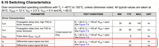
2. For a CANFD controller with 80% sampling points in a 2M data, in a real vehicle test environment, the falling edge time will exceed the 50ns which os over datasheet typical. If we want to ensure that the Daminant and Recessive are read correctly, what is the maximum limit for the falling edge time?

Lanxi

  • Hi Lanxi,

    Unterminated (high impedance) nodes are a large source of signal reflections in network systems. These reflections are much more impactful to the signal quality if they are from an unterminated node at the end of a long stub because the reflection will appear further from the original edge of the signal. The magnitude of these reflections can be reduced by adding partial termination (around 1.3k-ohms in this case) to dissipate some of the signal energy at the stub. This can show significant improvements in signal quality for networks with long or plentify stubs in the cable harness. 

    The fall time specification for our transceiver is specified over a typical load test condition with no cable harness connected. This specification is intended to be used to ensure that the transceiver is operating correctly in an evaluation environment. Once implemented into a system, the system characteristics can influence the timing of the signal to be outside the datasheet specification for the device alone. This does not mean that the signal is corrupted as the CAN protocol standard provides many other tools to deal with delays that are introduced at a system-level. 
    The actual maximum limit for these timing parameters will be unique for each system and will depend on many system-level factors, so I cannot answer briefly based on the specifications for the transceiver only. I can confirm that the datasheet specifications for transceiver behavior are not required to  be upheld in a system in order to achieve a robust solution. 

    Let me know if you have any more questions.

    Regards,
    Eric Schott