This thread has been locked.

If you have a related question, please click the "Ask a related question" button in the top right corner. The newly created question will be automatically linked to this question.

LMH0303: HD-SDI output amplitude and rise/fall time

Part Number: LMH0303

Tool/software:

Hello,

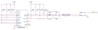
We use LMH0303 for HD-SDI output in our project, 2 such instances onboard.

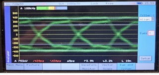
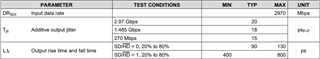
Measuring each of the 2 interfaces, the results we get are outside of Spec, in terms of amplitude, rise and fall time.

For channel 0, amplitude is 615 mV, rise/fall time is 450/452 pS, respectively.

For channel 1, amplitude is 704 mV, rise/fall time is 515/513 pS, respectively.

Video image looks ok, however it obviously does not correlate with the above mentioned values.

We have double-checked the circuit implementation and found it matching TI instructions (schematic diagram is attached).

The issue described seems very similar to the one addressed in this forum, however we couldn't find any solution summary:

https://e2e.ti.com/support/interface-group/interface/f/interface-forum/249891/lmh0303-sdi-driver-output-swing-rise-time-isues

We were able to tune the amplitude, changing Rref resistor, such that for channel 1, we got amplitude of 778mV, however no change whatsoever in rise/fall time.

Please advise about possible steps to fix this issue.

Thanks in advance,

  • Hi Arie,

    I noticed that in your schematic you have pulled the SD/HD# pin high. For slower rise and fall times, or ST 259 compliance, SD/HD is set high. For faster rise and fall times, or ST 424 and ST 292 compliance, SD/HD is set low. SD/HD may also be controlled using the SMBus, provided the SD/HD pin is held low.

    Best Regards,

    Nick

  • Hi,

    Thank you so much, will check this out.

    Best Regards

  • Hi,

    In addition to the pull-up, we have an FPGA driving this signal to Low (and we have double checked it is low).

    So, unfortunately, this is not the root cause.

    Best Regards

  • Hi Arie,

    Can you remove R2003 and see if there is an improvement? The pin voltage may be low, but because it is also pulled high, the operation is not guaranteed.

    Also, do you have a decoupling cap for Vcc?

    Best,

    Nick

  • HI,

    Sure, we will remove R2003 and check.

    We do have decoupling for VCC.

    Best Regards,

  • Hi,

    1. We have double checked and at the time we see Low on SD/HD# input, there is no pull-up (it has been removed).

    2. The initial values of amplitude and rise/fall time reported at the beginning of this thread, were measured externally to the system which includes the board      with LMH0303, at the monitor input, therefore they represent all the elements which affect the HD-SDI signal along the whole path (connectors and cabling inclusive).

    3. In order to isolate the factor which causes the violation of rise/fall time, we have measured the signal at the output of the filtering circuit (according to TI recommendations) applied on the LMH0303 SDO output pin (namely R2009, L2000, C2016 in the schematics), cutting off the remaining elements to monitor input (R2000 disconnected).

    Attached is snapshot of the values and signal - it shows that the LMH0303 signal output and associated filter circuit violates the Tr/Tf < 270 pS required by Spec. According to signal eye, there seems to be excessive loading, unexpected at the circuit output and without the additional connectors plus cabling.

    Can you please advise?

    Best Regards,

  • Hi Arie,

    Ok, thank you for providing more information about this case. As you've stated, 400+ picoseconds of rise and fall time is above spec for HD. I noticed that your input is 720p59 and your output is 1080p30, at what point does this video standard change?

    My main question when reading your description is: what is the rise and fall time at the output of your video generator and before the input to the LMH0303? Do you notice if the LMH0303 improves on or worsens the rise and fall time?

    One other thing to do is to check the LOS indicator. Is it stable?

    Best,

    Nick 

  • Hi,

    Thank you for follow-up.

    a). We generate the HD-SDI output from a "synthetic" pattern (not derived from input).

         We used different patterns, with same result.

    b). The previous screenshot you referred to, is from a Phabrix device which generates and analyzes SDI signals, and the 720 resolution is related to the generator, so it is not related to our issue.

    c.) I think this also answers your last question/s (generator Tr/Tf) and thus the LMH0303 Tr/Tf are dictated by the driver only.

    d.) By LOS do you mean Fault (pin 13)?

    I have a couple of questions:

    i) Looking at my latest shared results, it seems that the signal at the output of the LMH0303 driver and related filtering circuitry does not provide the expected quality, and this is after cut off of the real loading elements (cabling mainly, connectors, etc.)

    What does the experience with the same solution suggest, as far as the signal characteristics, as seen in the snapshot?

    ii) What is the use of the differential SDO, SDO# output? 

    We have kept the required balance on SDO# output, but I am concerned that it might affect somehow the quality of the SDO output, which we discuss?

    Best Regards,

  • Hi Arie,

    a). We generate the HD-SDI output from a "synthetic" pattern (not derived from input).

         We used different patterns, with same result.

    Can you give me more information about this synthetic pattern? Is it SMPTE, PRBS-10?

    d.) By LOS do you mean Fault (pin 13)?

    Yes, does it ever go low? Please try and sample it multiple times while the device is in operation.

    What does the experience with the same solution suggest, as far as the signal characteristics, as seen in the snapshot?

    When SD/HD# is low the typical rise and fall times are in the 90 to 130ps range.

    What is the use of the differential SDO, SDO# output? 

    Based on your schematic, the SDO# is terminated correctly. 75 ohms to ground. Additionally, since you are seeing rise times/fall times >300ps greater than typical, the problem is more likely due to the input signal not being SMPTE or PRBS-10 or the SD/HD# not being configured correctly. Can you try and set the SD/HD# pin low using SMBus writes? 

    Best Regards,

    Nick

  • Hi,

    Thanks for your support.

    1. Can you give me more information about this synthetic pattern? Is it SMPTE, PRBS-10?

    We have used some of the following patterns - SMPTE (lower res - 720p), Philips (1920x1080@30 Hz), see attached snapshots

    2. LOS/FAULT - we are going to monitor the signal

    3. SD/HD# - unfortunately we don't have SMBus writes currently available in our setup, however we are pretty sure it's "Low" because we disconnected

    the pull-up and measured with scope...

    BTW, a word regarding the patterns -- the Philips used is a good quality pattern (1920x1080@30 Hz), and for the SMPTE we couldn't find similar quality 

    (as mentioned, it's not driven by generator at the input -- this application doesn't have an HD-SDI input, therefore we use "synthetic" pattern driven to the HD-SDI output). Are you familiar with any downloadable SMPTE test pattern at similar resolution?

    Best Regards,

  • Hi Arie,

    I'm not familiar with any downloadable SMPTE test patterns. 

    therefore we use "synthetic" pattern driven to the HD-SDI output

    What do you mean by driven to the HD-SDI output?

    Best,

    Nick