This thread has been locked.

If you have a related question, please click the "Ask a related question" button in the top right corner. The newly created question will be automatically linked to this question.

TMUXHS4446EVM: USB3 connection clarification / error on EVM?

Part Number: TMUXHS4446EVM
Other Parts Discussed in Thread: TMUXHS4446

Tool/software:

Hi,

I'm working on a design based on this EVM. There's inconsistency between various docs on how to connect USB 3.0 to the host CPU so I'd like to clarify please

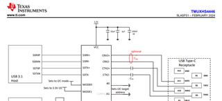
1. This doc: "TMUXHS4446 Evaluation Module SLAU882 – FEBRUARY 2024" shows a crossover between TX and RX between the micro USB B connector and TMUXHS4446. There also seems to be a mistake on the TX+ and TX- connections at the connector.

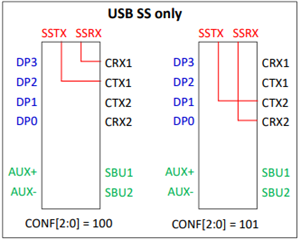
2. The datasheet for TMUXHS4446 (SLASF51 – FEBRUARY 2024) doesn't have a crossover from TX to RX on the USB3 host side. 

Is it a case that the EVM above is showing the design for sink sink rather than host side? Which connection scheme should I use for connecting TMUXHS4446 to the host CPU USB3.0 port?

thanks

Ciarán

  • Hi  Ciarán:

        For USB3, polarity swap is allowed  for USB spec.

       For this EVM, TX+/TX- swap was did on purpose for  layout  to avoid Vias.

      Also this EVM is only for source application only.

    Best

    Brian

  • Hi Brian,

    OK polarity swap was for better layout - understood.

    What about the TX connected to RX on USB?

  • Hi Ciarán,

    SSRX being connected to the TX of the Micro-B connector should be okay.

    The SSRX pins are connected directly to the CRX pins. This means that the signal is being received from the C-connector, going through the CRX pin, and then coming out through the SSRX. The SSRX pins are acting as a transmitter in this case to transmit the signal being received by the CRX pins out to the SSTX pins of the micro-B connector, when why SSRX is connected to SSTX.

    Please let me know if you have any other questions.

    Thanks,

    Ryan

  • Hi Ryan,

    Your explanation makes sense and I assumed it was correct since the EVM must work! I'm unclear as to why the datasheet shows otherwise but I guess I'll ignore that!

    I have now connected up the EVM and tested the USB side OK. I'm unable to detect a monitor through the EVM though having tried different DP sources and also trying to power from 5V barrel connector and also USB connector. I've checked the jumpers match those recommended in the user guide. Are there any known issues or tips in this area? Could it be related to the 'missing' caps on AUXP/N as per the datasheet that aren't on the EVM?

  • Hi Ciarán,

    Are there any known issues or tips in this area? Could it be related to the 'missing' caps on AUXP/N as per the datasheet that aren't on the EVM?

    As far as I am aware, there aren't any issues with using this EVM with a DP source and a type-c monitor for testing. The caps aren't present on the EVM because these caps indicated should already be provided by the host/source, and the device/sink. The provided document is more so for if the TMUXHS4446 is on the same board as the host or device.

    Would you be able to monitor the HPD jumper, JMP9, and see if thats pulling high? If it is, then that means that the source and sink can see each other, and that there should be some activity on the aux lines. You can check this by looking at the display settings of the host on windows, and seeing if the attached monitor is detected, but not enabled. If you can see the monitor is detected but there is no video, then there is likely an issue with the DP lanes, potentially needing different cables.

    Thanks,

    Ryan

  • Hi Ciarán,:

      Other than Ryan mentioned above, can you try with short DP cable?

    Best

    Brian

  • Hi Brian, Ryan,

    I tried this again today with another setup in the office and it worked first time. I'm not sure why it didn't work previously as I tried 2 different DP input sources and the monitor on the UCB-C side is the same model. The cables would be different so I'll back track to try and make sense of it and get the scope out if need be. Glad to see it all work OK now though. Thanks for help

  • Hi Ciarán,

    No worries! If anything comes up, please feel free to let us know.

    Thanks,

    Ryan

  • Final question Ryan!

    I can't tell from the documentation if the SPI flash is programmed on the EVM or not? If I don't have to worry about programming this all the better!

    thanks

    Ciarán

  • Hi Ciarán,

    Yes, the EVM comes with the SPI pre-programmed. There should be no worries there.

    Thanks,

    Ryan

  • Hi Ryan,

    So my concern in that case is where can I find the relevant file to copy this to my board, assuming I need it? It's not clear from the datasheet what this file is doing. Is this documented anywhere?

    Ciarán

  • Hi Ciarán,

    I believe the SPI flash on that board is used for the PD controller on the board, to ensure that it has the correct firmware. I don't believe it is required for using the TMUXHS4446, but I can double check.

    Thanks,

    Ryan

  • Hi Ryan,

    My design uses the PD controller also as my understanding was that I need this to get the display to work properly

    Rgds,

    Ciarán

  • Hi Ciarán,

    Yes, you would need that firmware to have it work properly. If you need the FW, please accept my E2E friend request, and I can send it over.

    Thanks,

    Ryan