This thread has been locked.

If you have a related question, please click the "Ask a related question" button in the top right corner. The newly created question will be automatically linked to this question.

[FAQ] DS320PR810: How should Gen 5 redriver power supply decoupling capacitors be arranged?

Part Number: DS320PR810
Other Parts Discussed in Thread: DS320PR1601, DS320PR410, SN75LVPE5412, SN75LVPE5421

Tool/software:

(Also applicable to DS320PR410, DS320PR1601, SN75LVPE5412, and SN75LVPE5421).

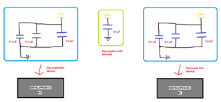
The datasheets for TI DS320PRxx and SN75LVPE5xx redrivers recommend the following sizes and numbers of power supply decoupling capacitors:

  • 0.1 uF, one for each VCC pin on a redriver
  • 1.0 uF, one for each redriver
  • 10 uF, one for each power bus that supplies power to one or more redrivers

What purpose do each of these capacitors serve, and what is the best way to arrange or structure them?

  • Here is more elaboration on the purpose and recommended implementation of each:

    • 0.1 uF capacitors - local VCC pin decoupling
      • These capacitors are small and suitable to help smooth out high-frequency noise that may be present on each VCC pin on the device.
      • Different redriver models may have as few as 2, or as many as 30 VCC pins
      • It is important during the PCB layout stage to place these 0.1 uF capacitors as close to the VCC pins as possible, and minimize the length of the trace leading to GND as well
        • Longer traces before or after the capacitor could result in stray inductance that is significant relative to the magnitude of 0.1 uF
        • On redrivers with QFN packages, these could be placed close to the perimeter of the device
        • On redrivers with BGA packages, the pins are commonly routed through vias, in which case the capacitors could be placed on the opposite surface layer of the board from the side that the redriver is installed on, as close to the VCC vias as possible.
    • 1.0 uF capacitor - general device decoupling
      • This is a medium size capacitor that helps one device in general with medium-frequency noise
      • Commonly, this can be placed in parallel with any one of the 0.1 uF local VCC capacitors on the device
    • 10 uF capacitor - bulk decoupling capacitor for one or multiple devices
      • This is a large capacitor operating on lower-frequency noise that is intended to help isolate the effects of one or more redrivers sharing the same 3.3 V power bus
      • Unlike the previous capacitors, the bulk capacitor is not specifically associated with any device in particular
        • Because of this, it is better to place it on the 3.3 V power rail in a separate location from the redrivers, especially if the design has multiple redrivers
        • For example, the TI DS320PR410 EVM with eight DS320PR410 redrivers, this capacitor is placed on the 3.3 V rail close to the voltage regulator that generated it.

    Here is a basic schematic sketch of these recommendations in an example where there are two SN75LVPE5412 devices (2 VCC pins each):

    Although redrivers are analog devices that don't need as much, or as precise supply decoupling as some other ICs, for best results it's still recommended to satisfy these minimum guidelines as best as possible.

    Additional decoupling on top of these minimum recommendations, such as using more capacitors or in a wider variety of sizes, can be done at the designer's preference. For example, if there's not a convenient spot on the board to place a shared 10 uF bulk capacitor, one can give every device its own local 10 uF capacitor instead. However we expect that in the majority of systems, these minimum guidelines discussed in the datasheet should lead to satisfactory power supply behavior while saving board and BOM space.

    Best,

    Evan Su