This thread has been locked.

If you have a related question, please click the "Ask a related question" button in the top right corner. The newly created question will be automatically linked to this question.

DS15EA101: Simulation models for ADS

Part Number: DS15EA101
Other Parts Discussed in Thread: DS30EA101, LMH0324, DS30BA101, LMH0302, TEST2, LMH1219EVM, LMH1219, LMH0397, LMH1297, LMH1297EVM

Tool/software:

Hi Team,

I am looking for a simulation model of the DS15EA101 or DS30EA101 that I can use to simulate transmission in ADS. The only model I could find is an IBIS model (thread title: "DS15EA101: IBIS Model" and DS30EA101 product page), but after checking the description of the IBIS models, it seems that it cannot be used as an Input-Output model. To see the effect of equalization on the devices, I need an IBIS IO model, a Touchstone file (s4p) or an IBIS-AMI.

I would be grateful if you could provide me the model I need.

Or could you introduce other equalizers with similar performance to DS15EA101 or DS30EA101 and with a model for simulating transmission in ADS? My application is as follows :
- LVDS
- 500Mbps
- 50Ω transmission line
- -22dB loss at 250MHz

Best Regards,

Naoki Yoneyama

  • Hi Yoneyama-san

    Unfortunately we only have the IBIS models for the DS15EA101 and DS30EA101 .

    For LVDS applications with 100 ohm differential transmission lines we have these two devices and IBIS files.

    Best,

    Nick

  • Hi Nick,
    If it's not limited to LVDS, are there any devices with similar functionality to the DS15EA101 or DS30EA101 that provide IBIS-AMI?

    Best,

    Naoki

  • Hi Naoki-san,

    For 75-ohm cable, you can consider LMH0324 and there is IBIS-AMI file that can be used for your modeling.

    Best,

    Nick

  • Hi Nick,

    Thank you for device recommendation.

    Could you send the IBIS-AMI model because I would like to consider LMH0324 on ADS simulation.

    Is there a low loss device that converts impedance from 50 ohms to 75 ohms for 500Mbps signal?

    Best,

    Naoki

  • Hi Naoki-san,

    Please accept my friend request. I will send you the IBIS-AMI model through a private message.

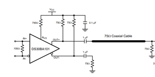
    The DS30BA101 is a low power option:

    Also, the LMH0302 is a possibility. The power consumption of the two devices is the same.

    Best,

    Nick

  • Hi Nick,

    I have accepted your friend request.

    Best,

    Naoki

  • Hi Nick,

    I'm considering using this device with an impedance conversion circuit converting from 50Ω to 75Ω. Could you tell me how to handle the pins.

    1)According to section5 in the datasheet, 4.7-µF AC coupling capacitors are required for IN0+/- and OUT0+/- in SMPTE video applications. How should I decide this capacitance value for 500Mbps encorded by 8b10b?

    2)How should I set Serial Control Interface pins if SPI or SMBus signals are not needed?

    3)As for MODE_SEL pin, which Level is proper if SPI or SMBus signals are not needed?

    4)How should I set OUT1+/- pins if I use only out0+/- under IN_OUT_SEL=F?

    Best,
    Naoki

  • I have sent the IBIS-AMI file

  • Hi Naoki-san,

    1. According to our similar LVDS devices a 1uF capacitor would be sufficient for the data rates that you have in mind.
    2. The Serial Control Interface pins and the MODE_SEL pin can be kept floating.
    3. The OUT1+/- pins can be left floating as well. However, to be on the safe side, it would be good to terminate the unused outputs.

    Best,

    Nick

  • Hi, Nick,

    Thank you for IBIS-AMI files and answer.

    I have simulated with the IBIS-AMI and Sparameter files of PKG and Termination. According to the datasheet, the input impedance of this redriver is 75 ohm but impedance definitions of PkgIN.s4p and rx0_term.s4p are 50 ohm. How is the input impedance of 75 ohm represented in these IBIS-AMI files?

    Best,

    Naoki

  • I have an additional question.

    Although I have trid a test simulation described as 7.2 Verification Test2 in "TI_LMH0324_IBIS_AMI_User_Guide.pdf", a example project attached IBIS-AMI zip file was terminated by error.

    I have changed the simulation settings a little and it ran without errors. The slightly changed settings I used are shown below. I think the problem is with "tx_term0.s4p". I want to use the VOD=0 setting, what should I do?

    <slightly changed settings>
    1. this is a described setting in the guide: EQ_Level=34, DEM=0, VOD=0 and tx_term0.s4p --->error
    2. EQ_Level=34, DEM=0, VOD=0 and tx_term1.s4p --->compleated
    3. EQ_Level=34, DEM=0, VOD=1 and tx_term0.s4p --->error
    4. EQ_Level=34, DEM=0, VOD=1 and tx_term1.s4p --->compleated

  • Hi Nick,

    I found the cause of the error. Only the spara files from "tx_term0.s4p" to "tx_term7.s4p" have frequency unit in GHz, and the files's data is on the order of THz. I thought that maybe the frequency unit is wrong, so I corrected it to Hz and the simulation completed successfully.

    Is the above correction correct? I'm also looking for your reply about 75 ohm impedance.


    Best,

    Naoki

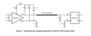
  • Naoki-san, a 50 ohm to 75 ohm impedance circuit is not recommended because it will cause reflections along the transmission line and compromise the signal integrity. For continued development we recommend using one of the two topologies:

    1) Using the DS30BA101 as a 50 ohm to 75 ohm conversion and DS30EA101 or LMH0324 as a redriver.

    2) Using 50 ohm impedance for the entire transmission.

    Best,

    Nick

  • Hi Nick,

    Thank you for the recommendation.

    1) I will try it. Could you sent the DS30BA101's IBIS-AMI model?

    2) I can not use 50 ohm impeadance for the entire transmission since in your products it seems that there is no simulation models of DS15EA101or DS30EA101, or other similer devices for 50Ω-cable. I have looked at other manufacturers products, but they do not provide simulation models for transmission so they are not my option for now.

    I would also appreciate it if you could tell me whether the frequency unit corrections in tx_term.s4p files are correct.

    Best,

    Naoki

  • Hi Naoki-san,

    Naoki Yoneyama said:
    PkgIN.s4p and rx0_term.s4p are 50 ohm. How is the input impedance of 75 ohm represented in these IBIS-AMI files?


    When I Check/View S-Parameters after clicking on rx0_term.s4p and then view the TDR plot of the s4p, I see the impedance rises to 75 ohms. This is also the case for the B1694A_coaxiModel_200m.s2p file.


    Naoki Yoneyama said:
    Is the above correction correct? I'm also looking for your reply about 75 ohm impedance.


    In the simulation, I am able to use tx_term0.s4p without changing the units for frequency. To set VOD to 0 I double-clicked on the IBIS_AMI icon, clicked on the AMI tab then set VOD to 0, and used tx_term0.s4p. The DS30BA101 IBIS model is on TI.com. Unfortunately, we do not have an IBIS_AMI model for the DS30BA101.

    Best Regards,

    Nick

  • Hi, Nick

    Using the same method as Nick, I was able to confirm that rx0_term.s4p changed from 50Ω to 75Ω. B1694A_coaxiModel_200m.s2p was also 75Ω. On the other hand, "PkgIN.s4p" was about 70Ω in a limited section, but was 50Ω in most sections. I understand that reflection occurs at the input of PkgIN.s4p, is that correct?

    Thank you for confirming the simulation model. So it means that the frequency of tx_term0.s4p starts from 20e15 Hz is correct. I unarchived example model again and set it up the same as Nick, but the simulation did not complete due to an error. My ADS version is 2024update2. What ADS version is Nick's?

    Best,

    Nick

  • Hi Naoki-san,

    Yes, reflections will occur at the input to PkgIN.s4p but the degree is important to note. If one clicks Check/View S-Parameters and notes S11 and S22 at low frequencies like 250 MHz, the return loss is not measured. The return loss at 1 GHz for PkgIN.s4p is near -30 dB. Note also the external 75 ohm pulldown resistors on PkgIN.s4p and example_ASIC_pkg.s4p that work to regulate the line impedance even though the TDR measurements read 50 ohms. The input impedance is not a concern for this example.

    I use ADS 2022 Update 2. 

    What is the the configuration that you would like to use for this design. Will you use the LMH0324 as a 75 ohm to 50 ohm retimer after a DS30BA101 (50 ohm to 75 ohm) cable driver? or opt for another configuration?

    Best Regards,

    Nick

  • Hi Nick,

    Our system uses 50 ohm cables and consider using LMH0324 as a equarizer to compensate cable loss. So I would like to as possible as include an effect of impedance mismatch between 50 ohm of cables and 75 ohm of LMH0324 to simulation. In my present simulation result including LMH0324's IBIS-AMI and S-parameters, the negative effect of impedance mismatch is little. Althought PkgIN.s4p does not contain values at low frequencies like 250MHz , I believe actual S11 at 250MHz is maybe same dgree at 1GHz and acceptable because LMH0324 supports from 125Mbps according to the datasheet.

    In ADS2022 update2, the same simulation error also occurs.

    I would like to evaluate LHM0324. Do you have LHM0324's Eva kit for diffrential input and output?

    Best Regards,
    Naoki

  • Hi Naoki-san,

    I checked and the LMH0324EVM is no longer available. Please use the LMH1219EVM instead. The LMH1219EVM has a 75 ohm input and 50 ohm differential output.

    Best,
    Nick

  • Hi Nick,
    Thank you for proposing alternatives. LMH1219 looks more suitable for our system because it has 100 ohm differential input. Could you senld it's IBIS-AMI model if you have?

    Best Regards,
    Naoki

  • Hi Naoki-san, 

    Yes, I will send the LMH1219 IBIS-AMI model by message right away.

    Best,

    Nick

  • Hi Nick,
    Thank you for the IBIS-AMI model.

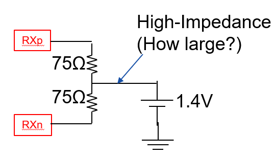
    Going back to the LMH0324, could you let me know a detail of the termination structure on receiver side? From the results of my simulation using LMH0324's IBIS-AMI and S-parameters, it looks like the 75 ohm is pulled down to GND, which divides the voltage and reduces the signal amplitude. Is the actual device terminated like that? If possible, I would appreciate it if you could explain the receiving termination structure using a diagram.

    Best,

    Naoki

  • Hi Naoki,

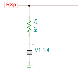
    I asked the design team for a reference, and they informed me that the receiver is connected by a 75-Ω to 1.4V (internal common mode voltage). As the LMH0324 datasheet states for IN0+ and IN0-: "Single-ended complementary inputs, 75-Ω internal termination from IN0+ or IN0- to internal common mode voltage and return loss compensation network"

    Here is a very simple diagram that may help to illustrate the scenario. Note that this is something I made and is not directly representative of the actual device structure.

    Best Regards,

    Nick 

  • Hi Nick,

    Thank you for creating an easily understandable diagram.
    Your diagram only shows the RXp port, but this device has differential inputs with both RXp and RXn and these are terminated to the internal common mode voltage of 1.4V. Is the following diagram correct as a more detailed representation of the termination structure? If my diagram is correct, could you please tell me approximately how large the resistance of the High-Impedance part is?


    Best,
    Naoki

  • Hi Naoki,

    You're welcome. The diagram is correct except that there is not a high impedance portion.

    Best Regards,

    Nick

  • Hi nick,
    I was be able to understand the termination structure.

    LMH0324 and LMH1219 can provide two outputs for one input using IN_OUT_SEL. If there are two outputs, will the amplitude be halved compared to the case of one output?

    Best Reagrds,

    Naoki

  • Hi Naoki-san,

    Hope you are doing well and no problem.

    In the case of dual outputs, the amplitude is not halved.

    Best,

    Nick

  • Hi Nick,


    It is good for me that the amplitude doesn't decrease by half.
    My current questions were solved.
    Thank you so much. You've been very helpful.

    Best,
    Naoki

  • Hi Nick,
    Could you please send me a programming guide for the LMH1219?

    Best regurds,

    Naoki

  • Hi Naoki,

    Please use this link to request the LMH1219 design files (including the programming guide):

    https://www.ti.com/drr/opn/LMH1219-DESIGN

    Best Regards,

    Nick

  • Hi Nick,

    I would like to confirm three points about LMH1219.

    1) According to the LMH1219 datasheet, the PCB equalizer for IN1 can compensate for the loss of a 20-inch board trace at 11.88 Gbps. What is the approximate dB loss that can be compensated at 500 Mbps?

    2) To change the strength of the equalizer, I can modify the setting at 0x03 on the CTLE/CDR Register Page. Is it possible to provide data on how the frequency characteristics of the CTLE change?

    3) Is there a register that allows changing the peak frequency of the IN1's CTLE?

    Best Regards,

    Naoki

  • Hi Naoki,

    1. The amount of dB that can be compensated for at 500 Mbps is not validated because the LMH1219 is validated with SDI datarates and 500 Mbps is above the 270 Mbps SMPTE signal. However, we have internal data that indicates that at 30 inches of input trace when the data rate is 270 Mbps the HEO value is still in the 0.98 UI range.
    2. and 3. The frequency characteristics and individual EQ adjustments for the IN1 equalizer are not publicly available.

    Best,

    Nick

  • Hi Nick,

    Happy New Year. May this year be your best ever.

    Could you find following my 2 questions?

    1)LMH0324 and LMH1219 have a cable equalizer for IN0 port. Can the equalizer be manually changed by resisters setting like a PCB equalizer for IN1 port of LMH1219 ?

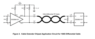
    2)As for DS15EA101, a recommended configuration for 100 ohm differential is shown in figure 3 on datasheet. though the 100 ohm is before AC coupling capacitors, Can I change the position of 100 ohm to after the capacitors? If there is some negative effect due to the change, please let me know.

    Best,

    Naoki

  • Hi Naoki,

    Happy New Year to you too. I sincerely wish the best for you and your family on this next year.

    1)LMH0324 and LMH1219 have a cable equalizer for IN0 port. Can the equalizer be manually changed by resisters setting like a PCB equalizer for IN1 port of LMH1219 ?

        -No it is not possible to adjust the IN0 equalizer using resistors.

    2)As for DS15EA101, a recommended configuration for 100 ohm differential is shown in figure 3 on datasheet. though the 100 ohm is before AC coupling capacitors, Can I change the position of 100 ohm to after the capacitors? If there is some negative effect due to the change, please let me know.

    I want to advocate for placing the resistors before the capacitors for two reasons;

    1) Placing the capacitor as close as possible to the device will reduce the loop inductance created by the trace length between the capacitor and the signal pin. By placing the resistor second, you are using layout space that will augment this negative effect.

    2) I have a minor concern about the low frequency content looping around the high speed traces when the AC cap is not present to block that content.

    Best Regards,

    Nick

  • Hi Nick,

    In many cases, since small chip resistors are used, I think the trace length will be shorter. However, is the effect of loop inductance still significant? From the perspective of eliminating the effects of reflections, I thought that it would be better to place the termination resistor as close as possible to the input pin. Which is more important when compared to the effects of loop inductance?

    Since AC capacitors will be placed, it seems that we don't need to worry about the effects of low-frequency components.

    Best,

    Naoki

  • Hi Naoki,

    I found a quote from a previous E2E that summarizes my point on AC caps:

    "AC cap, RX ESD structure, and connectors can all be seen as Discontinued Impedance Points along the PCB trace. If they are placed CLOSE ENOUGH, the Impedance  drop caused by AC cap(smaller) and RX ESD structure(larger) could be approximately seen as ONE Discontinued Impedance Point, so this is better for signal integrity. " -Quote

    I thought that it would be better to place the termination resistor as close as possible to the input pin. Which is more important when compared to the effects of loop inductance?

    I am not certain which is more impactful to signal integrity. I think I agree with you in saying that the resistor close to the pin will reduce reflections. Is it because you think the resistor will dissipate the reflected power?

    Best Regards,

    Nick

  • Hi Nick,

    Yes, I believe that even if reflections occur due to impedance discontinuities on the trace caused by AC cap and so on, the reflections will be dissipated at the input pin if there is a matching resistor. Furthermore, referring to the LMH0324, this device has a termination resistor internally, and an AC cap will be attached externally. This means that a termination resistor is placed after the AC cap.

    The configuration of placing a 100-ohm termination resistor before the AC cap is just one example, so is it also recommended to place a 100-ohm termination resistor after the AC cap?

    Best,

    Naoki

  • Hi Naoki,

    That's a good point. My main objection to placing the resistor after the capacitor was because of the possibility of a increased trace length, however, after discussion with you I am convinced that it would not be a long enough trace to cause problems, and that our other devices like the LMH0324 have a similar RX ESD structure without issues.

    As long as the impedance drop by the RX ESD structure is close enough to be seen as one impedance point, it sounds good to me.

    Best Regards,

    Nick  

  • Hi Nick,

    I'm glad to have reached an agreement on the position of the 100Ω termination.

    I would like to ask for additional confirmation regarding the LMH0324. I understand that the cable equalizer characteristics cannot be adjusted via registers, but is it possible to fix the EQ settings at the initial values without adaptation? While reviewing the datasheet, I noticed that adaptation takes 5m sec., which makes it unsuitable for the system.

    If the above measures are not possible, are there any other devices that meet the following requirements?

    - Equalization capability equivalent to the LMH0324

    - Ability to fix equalizer characteristics via register settings

       or turn off adaptation and fix equalizer characteristics at initial values

    - Availability of a simulation model

    Best,
    Naoki

  • Hi Naoki,

    Is using the OUT_CTRL pin on the LMH0324 sufficient for the application?

    The LMH0397 might be sufficient but it lacks the dual 100 ohm outputs that the LMH0324 has. Is that ok for the application?

    Best,

    Nick

  • Hi Nick,
    No, that is not sufficient. Using the OUT_CTRL pin bypasses the equalizer, but it is necessary to equalize the signal after cable in my application.

    Thanks for the alternative device suggestion. To determine whether the lack of a 100Ω output in the LMH0397 is an issue, confirmation through simulation is required. Can you provide the IBIS-AMI model?

    I would like to confirm whether the functionality of the LMH0397 is adequate.

    - Is it possible to set it up to use the cable equalizer for 500Mbps while not using the reclocker? According to Table 7, the desired configuration seems possible, but Table 6 suggests that 500Mbps may not be supported.

    - Can you provide the register map? I would like to confirm whether it is possible to disable equalizer adaptation and manually set the equalizer via registers.

    Best,

    Naoki

  • Hi Naoki,

    Please see the programming guide and IBIS model in your messages:

    TI does have other equalizer devices that do not have a 75 ohm input, and if you are bypassing the reclocker, SDI devices are more expensive for the features that you get.

    Best Regards,

    Nick

  • Hi Nick,

    Thank you for providing the guide and simulation model. However, the model appears to be for the LMH1297. Does this mean that the simulation models for the LMH0397 and LMH1297 are the same?

    At this point, I prioritize achieving the desired functionality over cost.

    I would also like to request information about other devices. I have organized the conditions required for the device as follows:
    - The ability to turn off the equalizer adaptation and fix the characteristics
    - No reclocker is needed; if a reclocker is present, it should be bypassable
    - A simulation model can be be provided
    - Capability to 500Mbps
    - Ability to compensate for cable losses
    - The configuration of input and output termination is of lower priority; I will confirm its applicability to my system through simulation.

    Best,
    Naoki

  • Hi Naoki,

    Yes that is correct, the simulation models are the same besides the data rate.

    I do not have an extensive knowledge of other cable equalizers that TI produces, because my area of expertise is in SDI devices. 

    The ability to turn off the equalizer adaptation and fix the characteristics

    Allow me until next week to do some validation on this though to confirm it is possible.

    No reclocker is needed; if a reclocker is present, it should be bypassable

    LMH0397 has a reclocker, but it is bypassable.

    A simulation model can be be provided

    LMH0397 has an IBIS-AMI model nested within the LMH1297 IBIS AMI model under the schematic name "cable"

    Capability to 500Mbps

    This is possible but is not validated

    Ability to compensate for cable losses

    LMH0397 has a cable equalizer and can compensate for up to 600m of Belden 1694A cable at 270 Mbps.

    The configuration of input and output termination is of lower priority; I will confirm its applicability to my system through simulation.

    Sounds good keep me updated.

    Best Regards,

    Nick

  • Hi Naoki,

    Allow me until next week to do some validation on this though to confirm it is possible.

    I confirmed that it is possible to manually adjust the equalizer value.

    Best Regards,

    Nick

  • Hi, Nick
    Thank you for the important operational confirmation.  I have three questions, so please see below for details:

    1. Does "I confirmed that it is possible to manually adjust the equalizer value" mean that you were able to manually adjust the EQ characteristics using register 0x24 on the ConfigIO register page?

    2. I understand how to adjust the EQ adaptation value using register 0x24, but I do not know how to turn off the Cable EQ adaptation. Could you please provide the register settings for that?

    3. According to the datasheet, it seems that in EQ Mode, the equalized data can be output from OUT0 at 100Ω while bypassing the reclocker when inputting to SDI_IO. Is that correct?

    Best,

    Naoki

  • Hi Naoki,

    . Does "I confirmed that it is possible to manually adjust the equalizer value" mean that you were able to manually adjust the EQ characteristics using register 0x24 on the ConfigIO register page?

    Yes, use the following sequence on the LMH0397:

    Command Register Value Mask
    //Select the ConfigIO page 0xFF

    0x05

    0x05

    //Disable EQ Adaptation 0x00

    0x40

    0x40
    //Write to the EQ value 0x24

    xx

    0x1F
    //Check the EQ value 0x25

    xx

    0x1F
    3. According to the datasheet, it seems that in EQ Mode, the equalized data can be output from OUT0 at 100Ω while bypassing the reclocker when inputting to SDI_IO. Is that correct?

    Yes, depending on the OUT_CTRL pin setting, you can bypass the reclocker.

    Best Regards,

    Nick

  • Hi Nick,
    Thank you for the response and the register sequence.

    I intend to start working on the simulation using IBIS-AMI. There are a few points I do not understand regarding the AMI settings:

    - In Rx-AMI, what does DWDM_mode refer to?

    - In Tx-AMI, OUT_DA_SEL is used to switch between UHD/HD/SD drivers. What changes when the driver is switched with this setting?

    Best,
    Naoki

  • Hi Naoki-san,

    Please allow us to review your questions and get back to you early next week.

    Regarding DWDM, I found this older E2E post about this model.

    Best,
    David

  • Hi Naoki,

    LMH0397/1297 uses the same IP from our Ethernet devices which support DWDM mode. DWDM has not been used or characterized with the LMH0397 device. We should not use this bit. DWDM mode bypasses the equalizer stages.

    - In Tx-AMI, OUT_DA_SEL is used to switch between UHD/HD/SD drivers. What changes when the driver is switched with this setting?

    I do not know how it effects the drivers. This could be something you have to investigate given that UHD,HD ,and SD are not used.

    Best Regards,

    Nick