Part Number: SN65DPHY440SS
Tool/software:
We are currently working on a PTZ camera surveillance system utilizing the SN65DPHY440SSRHR Retimer to extend MIPI HS signal lengths.
The current issue is: we are encountering a random momentary stuck issue.
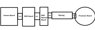
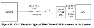
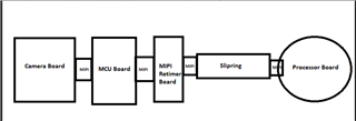
The total MIPI length is approximately 650 meters, with signals passing through various boards from the camera to the processor, please refer below image,
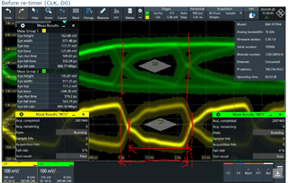
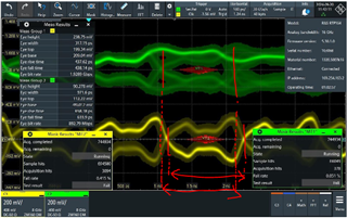
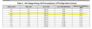
We have also observed that the eye diagram fails both before and after the MIPI retimer IC. Could you please investigate the Retimer IC and provide guidance on potential changes we can implement to better tune the MIPI signals? We have tested with the default hardware configuration for the MIPI retimer.
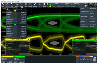
Before re-timer (CLK, D0)
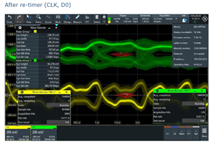
Also, observed that the MIPI clock datarate after retimer is changing from the original 890Mbps to 1.9Mbps.