This thread has been locked.

If you have a related question, please click the "Ask a related question" button in the top right corner. The newly created question will be automatically linked to this question.

DS90UB960-Q1: Image Tearing Issues

Part Number: DS90UB960-Q1

Tool/software:

Good afternoon,

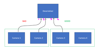
We've looking for some assistance with video "tearing" when using the DS90UB960WRTDT-Q1 deserialiser paired with a DS90UB953TRHBR-Q1 serialiser, which in turn is connected to a 2MP 1080p image sensor operating at 60fps. Our problem seems to occur when we have 2 x DS90UB953TRHBR-Q1 serialiser devices connected to a single port pair (IE, Camera port 0 & 1, Camera port 2 & 3). The problem does not occur if we have multiple cameras across multiple port pairs (IE, Camera port 0 & 3, Camera port 1 & 4).

We have performed countless MAP analyses on the deserialiser with the serialiser connected to all four camera ports and all provide MAP results far exceeding the minimum requirements shown in SNLU24.

We're a bit confused as to what is happening when this "tearing" situation occurs. We believe it may be something to do with the output stream from the deserialisers MIPI CSI-2 ports. For context:

1. Our deserialiser is set to CSI-2 synchronous operation with virtual channels enabled.

2. REFCLK is 25MHz.

3. Maximum data rate per image sensor (per channel) = Horizontal x Vertical x Bits per pixel x Frame Rate x Overhead = 1920 x 1080 x 10 x 60 x 7.5% = 1.338Gbps which is significantly lower than the 160 x REFCLK = 4Gbps forward channel rate mentioned in the datasheet.

4. CSI-2 transmitter frequency has been set to 800Mbps per data lane with continuous CSI-2 clock operation.

5. Best-effort round robin CSI-2 forwarding has been enabled on CSI-2 ports 0 & 1. RX ports 0 & 1 are forwarded to CSI-2 port 0 and RX ports 2 & 3 are forwarded to CSI-2 port 1.

Taking our calculations from above, when two cameras are on a single port pair, we should have 1.338Gbps x 2 = 2.668Gbps across four CSI-2 data lanes. 2.668Gbps / 8 = 334MBps is therefore sent across these four CSI-2 data lanes, which is CSI-0 (port 0) in the datasheet.

To work out the maximum bandwidth of CSI-0 (port-0), we can work out equation (2) on page 45 of the datasheet:

  • Hactive = 1080 pixels
  • Nsensor = 2
  • Ncsi_lanes = 4
  • Nbits/pxl = 10 bits
  • fcsi = 800MHz
  • tcsi = 0.93us

This gives us an a maximum bandwidth of 2.51Gbps / 8 = 314MBps.

Could you please confirm whether the above is true? If our calculations are correct, does this mean we're over the maximum CSI-2 transmitter bandwidth of the deserialiser and to resolve this issue, we should increase the CSI-2 Tx data rate?

Any assistance you can provide would be greatly appreciated. If you would like me to send our schematic, layout, MAP results or I2C configuration, I'd be happy to share so long as we can take this conversation private.

Many thanks for your time.

Connor.

  • Hello Connor,

    I am not sure I understood what you mean by the following. What do you mean by 2 cameras connected to a single port pair or multiple port pairs?

    Our problem seems to occur when we have 2 x DS90UB953TRHBR-Q1 serialiser devices connected to a single port pair (IE, Camera port 0 & 1, Camera port 2 & 3). The problem does not occur if we have multiple cameras across multiple port pairs (IE, Camera port 0 & 3, Camera port 1 & 4).

    Can you also explain what do you mean by video tearing?

    Can you provide your applied register settings to the SER and DES in all cases, working and non working? and register dumps for the same

  • Hi Hamzeh,

    Apologies for the confusion. Hopefully this image and the below explanation clear things up:


    • When Camera 1 is plugged into deserialiser FPD port 1 on it's own (IE, no other cameras plugged into any other ports on the deserialiser), video quality is excellent.
    • When Cameras 1 and 2 are plugged into deserialiser FPD ports 1 and 2, video quality is poor on both Cameras 1 and 2 (tearing occurs).
    • When Cameras 1 and 3 are plugged into deserialiser FPD ports 1 and 3, video quality from both Cameras 1 and 3 is excellent.
    • When Cameras 1 and 4 are plugged into deserialiser FPD ports 1 and 4, video quality from both Cameras 1 and 4 is excellent.
    • When Cameras 3 and 4 are plugged into deserialiser FPD ports 3 and 4, video quality is poor on both Cameras 3 and 4 (tearing occurs).

    By "tearing", I'm referring to visible screen tearing of the images presented from the camera to the display (https://en.wikipedia.org/wiki/Screen_tearing).

    If I have Cameras 1 & 2 plugged in to the deserialiser and I wave my hand in front of the cameras, I get screen tearing on our video feed from both cameras. If however I then remove Camera 2 and still have Camera 1 plugged into the system, the video quality from Camera 1 returns to an excellent condition.

    Register settings for SER and DES attached below.

    Many thanks,

    Connor

    DES-SER-REG

  • Hello Connor,

    As per your Video data bandwidth calculations we do have ~1.34Gbps/Camera. When you connect 2x Cams using the same DES CSI-2 TX port, the total amount of video will be ~ 2068Gbps/ port. On the same time, you are using only 2x CSI-2 TX lanes on the DES @ 800Mbps/lane. Which makes the max amount of supported data rate is ~1.4Gbps/port (after subtracting the CSI-2 Overhead).

    In order to your system to work without errors, the DES CSI-2 TX bandwidth must be greater than the incoming data rate, which is the opposite here.

    Hence, at the DES TX, you must use either 4x CSI-2 lanes @ 800Mbps/lane, or 2x CSI-2 lanes @ 1600Mbps/lane

  • Hi Hamzeh,

    From my understanding, we're using 4 x CSI-2 TX lanes as we've set CSI_CTL to 0x03 on both CSI-TX port 0 and port 1. As mentioned previously, "...when two cameras are on a single port pair, we should have 1.338Gbps x 2 = 2.668Gbps across four CSI-2 data lanes."

    Yet when I put these parameters into equation (2) given on page 45 of the datasheet:

    • Hactive = 1080 pixels
    • Nsensor = 2
    • Ncsi_lanes = 4
    • Nbits/pxl = 10 bits
    • fcsi = 800MHz
    • tcsi = 0.93us

    The equation gives us an a maximum bandwidth of 2.51Gbps which is less than the 2.668Gbps required by our system.

    Many thanks,

    Connor 

  • Hi Connor,

    The equation gives us an a maximum bandwidth of 2.51Gbps which is less than the 2.668Gbps required by our system

    are you planning to reduce your data rate to fit within the available bandwidth?

  • Hi Hamzeh,

    Ideally, no we won't be reducing the data rate to fit within the available bandwidth. We need our system to operate at 1080p at 60 fps however, we're still struggling to understand what the correct maximum bandwidth of the CSI-2 ports are.

    What is confusing us is your previous comment:

    Hence, at the DES TX, you must use either 4x CSI-2 lanes @ 800Mbps/lane, or 2x CSI-2 lanes @ 1600Mbps/lane

    Our register maps are setup to allow 4 x CSI-2 lanes @ 800Mbps/lane but this is not the BW limit. Instead, the BW limit when using Best-Effort Round Robin CSI-2 Forwarding, it is what we've calculated above = 2.51Gbps.

    So our question becomes what configuration should the deserialiser be in to achieve support for a 2-MP sensor at 1080p resolution at 60-Hz frame rate? Simply increasing the data rate to 1.6Gbps/lane did not resolve the issue.

  • Hello Connor,

    It looks like I misunderstood you. If you are using each 2x Cameras connected to 1x CSI-2 TX port with 4 lanes @ 800Mbps/lane, then your output bandwidth should be fine (I though you are using just 2x CSI lanes per port)

    If you provide me with register dumps from SER and DES, then I can help reviewing it.

  • Hi Hamzeh,

    Apologies for the delay in responding to you.

    Thanks for the clarification on lane calculations. Please see the attached files as requested.

    UB960 Register Dump

    UB953 Register Dump

    Note that the UB960 register read was taken with 2 x cameras plugged into FPD Link Rx ports 0 and 1. The UB953 register read was taken from a camera installed on Rx port 0.

  • Hi Connor,

    I was confused, what are the numbers in the 'Success' column. Now it is clear, these are the read value for each specific register. I was confused because everything is in HEX but these numbers are DEC.

    However, this UB960 register dump is not valid. This read is from RX port 3, but your cameras are connected to RX ports 0 and 1. 

    Since most of the registers are port specific, you need to follow these steps in order to dump the correct registers:

     write 0x4C = 0x01 # to select RX port0 registers

    dump all registers

    write 0x4C = 0x12 # to select RX port1 registers

    dump all registers

    Once you provide the new dumps, can you please make sure all dumps are in HEX not DEC? thanks

  • Hi Hamzeh,

    Please see attached as requested.

    RX0 Output (Hex)

    RX1 Output (Hex)

  • Hello Connor,

    I have reviewed your register dumps. I can see the following errors on both RX ports:

    reg 0x4D - LOCK status changed
    reg 0x4E - Line length and line count changed

    However, the received data type and resolution on both RX ports are correct as expected. 

    Reg 0x73 = 0x04
    Reg 0x74 = 0x38
    ==>> 0438 hex = 1080 Dec : Number of Lines

    Reg 0x75 = 0x09
    Reg 0x76 = 0x60
    ==> 0960 hex = 2400 Dec : Number of Bytes
    2400x4/5 = 1920 Dec : Line length

    Just one question needs your confirmation:

    You are reassigning the following VC IDs to the incoming data. All incoming VC IDs on RX0 are reassigned to 0. But on RX port1 you are reassigning VC IDs 1, 2, 3 to 0, but VC ID 0 to 1. Is that expected?

    Please check these settings and compare it to what your SoC is expecting. Because I do not see any serious issue on the DES or its settings.

  • Hi Hamzeh,

    Thanks for confirming received data type and resolution are correct. Do you have any insight as to why the LOCK status and line length/count registers are reporting errors when 0x73-0x76 are reporting correctly?

    I'm not sure I understand your question about the VC IDs.

    We set 0x72 on RX port 0 to 0x00 which maps all incoming data on Rx port 0 to a VC-ID of 0.

    We set 0x72 on RX port 1 to 0x01 which maps all incoming data on Rx port 1 to a VC-ID of 1.

    This is also the same for Rx port 2 (0x72 = 0x02) and Rx port 3 (0x03).

  • Hello Connor,

    Do you have any insight as to why the LOCK status and line length/count registers are reporting errors when 0x73-0x76 are reporting correctly?

    The LOCK status and Line length/count bits are clear on read bits. I believe that these errors are reported at the very beginning of transmission/bring up. To make sure that this is the case, you may need to dump these registers two times with few minutes delay in between.

    We set 0x72 on RX port 0 to 0x00 which maps all incoming data on Rx port 0 to a VC-ID of 0.

    We set 0x72 on RX port 1 to 0x01 which maps all incoming data on Rx port 1 to a VC-ID of 1.

    This is also the same for Rx port 2 (0x72 = 0x02) and Rx port 3 (0x03).

    Do you mean that you are receiving only VC-ID 0 from all Cameras? Are you sure there is no other VC-ID? If that is the case, then you should be okay.

  • Hi Hamzeh,

    That is correct - We are only receiving VC-ID 0 from all cameras. We're confident there are no other VC-IDs though we will verify this as its a good point to raise.

    We will continue investigating the tearing issue as it's entirely possible that the issue comes from post-deserialiser processing.

    Many thanks,

    Connor

  • Hi Connor,

    Thanks for the info.

    I will go ahead and close this ticket for now. However, if you have any questions, you can just post them here and the ticket will be re-opened automatically.