


Part Number: DS125DF1610
Other Parts Discussed in Thread: DS110DF1610
Tool/software:
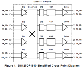
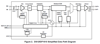
DS125DF1610 and DS110DF1610 are 16-channel retimers which implement 4x4 crosspoint switches.
There are 2 registers which need to be configured to use the crosspoint: channel registers 0x96 and 0x9B.
- 0x96[5]: This bit should always have value 0. Channels should always have master control.
- 0x96[4:2]: All three of these bits should have value 1 on channels using crosspoint functionality. Bit 4 enables the crosspoint and bits 3:2 enable both the local and multi-drive buffers.
- 0x96[1:0]: These bits define where the high speed data is coming from. They select which channel input will be connected to the output of the channel whose register set is selected.
- 0x9B[1:0]: These bits define which channel output the CTLE should be connected to. They select which channel output will be connected to the input of the channel whose register set is selected.
- All other register settings are from the perspective of the output channel. For example, if Rx0A is connected to Tx0B, channel 0B registers correspond to all functional blocks of this signal path.
Here is an example of a crosspoint configuration.
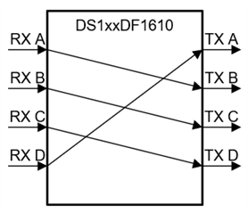
| Channel | Reg 0x96 Value | Reg 0x96 Comment | Reg 0x9B Value | Reg 0x9B Comment |
| A | 0x1F | Connects RX D to TX A | 0x01 | Connects RX A to TX B |
| B | 0x1C | Connects RX A to TX B | 0x02 | Connects RX B to TX C |
| C | 0x1D | Connects RX B to TX C | 0x03 | Connects RX C to TX D |
| D | 0x1E | Connects RX C to TX D | 0x00 | Connects RX D to TX A |
The DS125DF1610 and DS110DF1610 SigCon Architect GUI profiles have a bug on the Crosspoint Switch tab. Configurations made on this tab do not program register 0x9B correctly. Please verify low level register values are programmed correctly when configuring the crosspoint using the GUI.