A related question is a question created from another question. When the related question is created, it will be automatically linked to the original question.
If you have a related question, please click the "Ask a related question" button in the top right corner. The newly created question will be automatically linked to this question.
It is possible to use 4 LM5177 to support 1kW. For less ripple, you can use an external clock with 90 degree phase shift for 4 phases. I will involve the clock team to suggest a device for that.
The MOSFET used in our EVM is not suitable for your case. I'm not a MOSFET expert, but hopefully I can give you some suggestions about selecting the right part.
You can use our Power Stage Designer tool to find the max ratings of the MOSFET in your design: POWERSTAGE-DESIGNER
Important features of the MOSFET to focus on are the max ratings of the Drain-source voltage, drain current and also the gate charge. The VCC regulation voltage of LM5177 is 5V and it needs to be able to drive the MOSFET.
For the clock, you can use the clock generator suggested in the app note if the clock team doesn't have a better suggestion.
I am not certain if the LMK01801 (driven by LMK6C) can support digital delay for this low of a frequency range (<= 600kHz) - I have assigned this to our buffer expert for further investigation.
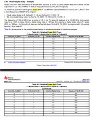
This is possible with this device. One suggestion I have - make the output frequency the ref clk divided by 8 - this guarantees you can meet the 90,180,270 deg phase shift with the following settings.
So, in other words, if you have output set to 500kHz make the ref clk 4.5MHz - this will make the ratios the same as table 9-3 and now you can just set CLKOUT12_13_DDLY to 7 and CLKOUT12_13_HS to zero which results in a relative digital delay of 2.0 steps which is a 90-degree phase shift.
If you don't choose to follow this - you will find yourself forced to manually do the math to calculate the respective half period and relative digital delay steps to create the phase shift you require.