THS6232RHFEVM: Arinc 429 Transmitter with a THS6232 line driver

Part Number: THS6232RHFEVM
Other Parts Discussed in Thread: THS6232,
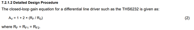
Tool/software:

Hi, I'm currently looking to implement an ARINC 429 transmitter.

A basic functional overview would be, a controller sends a signal that swings 3.3V to GND and the transmitter outputs a differential +-5V and Null (high Z) 

I have made a previous post describing a comparator based circuit here: https://e2e.ti.com/support/amplifiers-group/amplifiers/f/amplifiers-forum/1415991/lm2901av-comparator-based-arinc-429-reciever-transmitter

The issue discussed in that post was mainly not being able to drive a fully loaded bus of 20 devices (12.5mA) in addition to not being able to propagate a null condition with only comparators. It seems like the addition of the THS6232 to the output stage of the previous circuit would solve both of these issues. I've attached the circuit I'm describing below.

My question is if my description of function feasible with the THS6232? That is, can I feed the +-5V output of the above circuit, after moving the terminating resistors to the output of the driver, to the line driver and source line loads in excess of 12.5mA at +-5V to gnd? And would I also be correct in assuming that I can use the bias pins of the THS6232 in order to have both lines be high impedance? 

Appreciate the help, Jacob

  • Hello Jacob,

    You can use the THS6232's bias modes to control current draw and put the device into power down.  While in power down the THS6232's outputs are high-impedance, but do be aware the feedback resistors will still provide a path for voltages on the output to drop across.

    Will the THS6232 be driving the lines directly or through coupling or a transformer?

    You can sample & order THS6232RHFEVM if you would like to test out any output network changes.  The output transformer can be removed and shorted with zero-Ohm resistors or coupled using capacitors.

    Best,

    Alec

  • Hi, Alec

    Will the THS6232 be driving the lines directly or through coupling or a transformer?

    I believe through coupling shown below. 

    You can sample & order THS6232RHFEVM if you would like to test out any output network changes.  The output transformer can be removed and shorted with zero-Ohm resistors or coupled using capacitors.

    I think it'll be a little cheaper to spin my own board with a lot of 0 ohm jumpers for my purposes. 

    Thanks, Jacob

  • Hello Jacob,

    Thank you for sharing the coupling structure. If it will help you develop and test with THS6232, I can assist in sending samples of the devices or an evaluation board.  

    Please connect with me via e2e if you would need assistance in this.  In the interim I’ll continue to help answer any questions as well as consider the information you shared already. It would be good to see THS6232 used in ARINC-429 systems.  

    Best,

    Alec

  • Hi Alec, 

    If I do not want voltage gain and just need to source current under high loads should I just make Rg in the equation in section 7.2.1.2 of the data sheet a very high value? Since the equation will only approach 1 I wasn't sure if I was missing something.

    Thanks, Jacob

  • Hello Jacob,

    Since the THS6232 is a current-feedback amplifier, the Rf value does affect bandwidth and stability.  For your use-case, I would suggest 2kOhm Rf as a starting point.  The THS6232 has a listed minimum stable gain of 5V/V, so you may find you need to apply some gain.  You may find the device performs in unity-gain to your needs.

    For current-feedback op-amps you need an Rf feedback resistor even in a unity-gain buffer setup.  

    Best,

    Alec

  • Thanks, That is good to know. 

    I think I will start with Av = 5V/V, In this case Rg will be around 1K correct? What will Rf and Rg look like at unity-gain? 

    Jacob

  • Hello Jacob,

    We actually have a few curves in the datasheet 'Typical Curves' section using Rf = 1.5kOhms for gain of 5V/V; the resulting Rg would be 375 Ohms (on EVM this would be split for both Rf1 & Rf2, so the value would be 750 Ohms).

    For unity gain I would try a higher Rf resistor value, like 2kOhms.  You would float/not place an Rg resistor here, similar to how you would implement unity gain with a voltage feedback amp.  The key is you still need Rf; Rf does not set the gain in a unity-gain configuration, but rather it affects your amplifier bandwidth.

    Best,

    Alec