This thread has been locked.

If you have a related question, please click the "Ask a related question" button in the top right corner. The newly created question will be automatically linked to this question.

DS160PR1601: DS160PR160 connect failed

Part Number: DS160PR1601
Other Parts Discussed in Thread: DS320PR1601, , USB2ANY

Tool/software:

Hi,Experts 

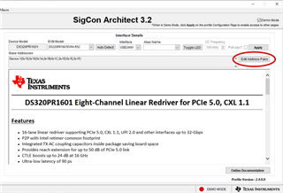
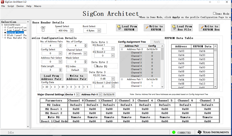
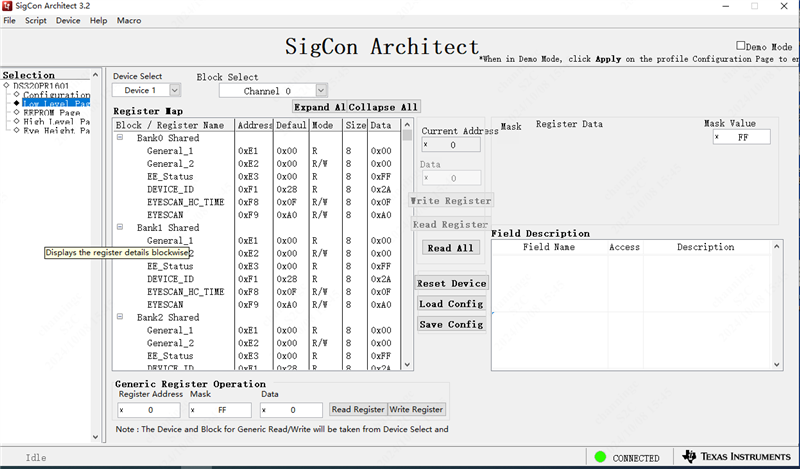
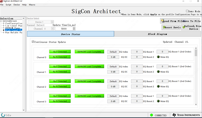
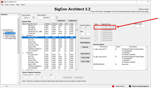
I use the SigCon Architect profile for the DS320PR1601 in order to configure DS160PR1601. When I connect the DS160PR1601, the SigCon Architect will report a Error like below: 

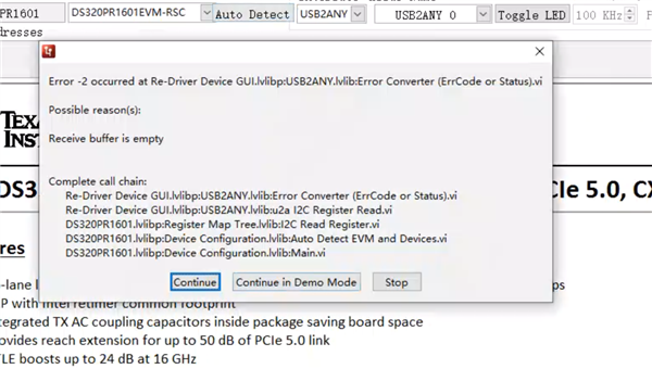
Could you give me some advices to resolve this issue ? 

Thanks 

Powell

  • Hi Powell,

    Thank you for reaching out. Please provide some additional details for us to help debug your issue.

    • Could you please list the SigCon Architect profile version being used? This is listed in the bottom right-hand corner of the DS320PR1601 GUI profile.
    • Is the DS160PR1601 being used on a custom design? If so, is this a motherboard or add-in-card?
    • Could you please verify that the SMBus address settings of the SigCon Architect GUI profile match the SMBus addresses selected using the ADDRx pins of the device?
      • The SMBus addresses can be modified in the SigCon Architect GUI profile by selecting the "Edit Address Pairs" button.
    • Could you please verify that the I2C connections from the USB2ANY are connected to the correct SMBus pins of the DS160PR1601?
    • Are there any other SMBus devices connected to the SMBus which the DS160PR1601 uses which could be using conflicting or shared SMBus addresses?

    Best,
    David

  • Hi, David 

    Thanks for your supports. 

    Now the USB2ANY can connect to DS160PR1601 normally. 

    But we encounter a another question, the PCIe device can't link. Could you please check if the following configurations are correct ? Or please give some advices to debug this issue? 

    Thanks 

    Powell

  • Hi Powell,

    Thank you for confirming that the connection to the USB2ANY and DS160PR1601 are now functioning as expected.

    The redriver contains programmable CTLE settings (EQ Index, DC Gain). Without knowing much about the system topology that is under test, I would suggest to begin with a low EQ Index (0), program the device, and subsequently re-train the link to establish link-up with the device. You may find this application note to be a helpful reference.

    Best,
    David

  • More Info, when I use the FPGA as a PCIe endpoint and connect it to a PC through Redriver, the FPGA's PCIe state machine shows that it cannot complete "detect".

    However, the loopback test from FPGA -> redriver -> FPGA works fine. And redriver show all lane has detected.

    Is there any register that needs to be adjusted? or is there an error in its use

  • Hi Powell,

    Thanks for providing more information. Generally there aren't register settings on the DS320PR1601 that need to be adjusted to enable a connection, especially if the device is already working in another configuration. Have you tried a direct connection from the FPGA to the PC? From there you could determine whether the issue is with the redriver or with the PC.

    Best Regards,

    Nick

  • Hi, Nick 

    Thanks for quick respone. 

    We have already tried the FPGA to the PC with OSS cable solution, It works fine, so I think the FPGA and PC are good. 

    In order to explain clearly, the application block diagram are attached.

    1、Connect to PC, the PCIe can't Link.

    2、Loopback test works well, the speed can run up to 16Gbps.  


    1、According to the results of Loopback test, can I assume that the connection of the channesl are OK? 

    2、There are 64 integrated AC coupling capacitors on TX pins inside DS160PR1601, if the excess decoupling capacitors in the path will affect the PCIe link?

    Best Regards

    Powell 

  • Hi Powell,

    David and Nick will be back in the office on Monday to answer your questions in full, but I can comment right now on your second question:

    2、There are 64 integrated AC coupling capacitors on TX pins inside DS160PR1601, if the excess decoupling capacitors in the path will affect the PCIe link?

    PCIe signals are expected to be AC-coupled exactly one time, therefore the TX signals leaving the DS160PR1601 should not be AC-coupled again by external capacitors. Coupling two times shifts the effective capacitance to an unexpected value and could have negative effects on the signal quality.

    I would also note that the typical value for the AC coupling capacitor in PCIe designs is 0.22 uF - from your block diagram, it looks like 0.1 uF is being used. So any further deviations from the expected capacitance could potentially cause signal integrity problems. However at this time I don't know if the communication problem has been definitely narrowed to a SI problem yet.

    Best,

    Evan Su

  • Hi, Evan

    We remove the AC coupling capacitors on the FPGA RX side, the PCIe' LTSSM still can't detect any receivers on lanes.

    Then we tried in following connect, the PCIe can link up, and the speed can be up to 16Gpbs.  It looks like PCIe can link as long as RX is detected.

    Why the redriver's Receiver Detect State Machine show all lane detect, but the FPGA's PCIe LTSSM shows none of Receivers detected on any Lane?  Could you provide some clues to debug this issue ? 

    Thanks 

    Powell


  • Hi Powell,

    Could you please re-upload the second image from your reply? The image does not appear to be loading correctly from my view.

    When you state that the redriver's RX Detect State Machine shows all lanes are detected, could you please specify what page of the GUI you are using? To verify, could you please check the value of the RX_DET_STS for some of the DS160PR1601's Channels in the SigCon Architect GUI's Low Level Page? If proper termination is seen, I would expect RX_DET_STS[7:6] = 0b11 for each channel which sees proper termination.

    Best,
    David

  • Hi, David 

    Please find the second image below:

    And after our tests, we found that if the TX side of Endpoint has AC coupling capacitors, the Receiver can be detected on the Lanes. 

    Is there any why to bypass the driver's decoupling capacitors or the redriver ? 

    Best, 
    Powell

  • When you state that the redriver's RX Detect State Machine shows all lanes are detected, could you please specify what page of the GUI you are using?

    We use the low level page: 

    Best,

    Powell

  • Hi Powell,

    Thank you for including the second image in your latest reply.

    Per PCIe Spec, all TX are required to be AC coupled. So, adding these AC coupling capacitors to the FPGA Endpoint's TX is necessary if they are not already integrated into the FPGA's TX package.

    It is not possible to bypass the internal AC coupling capacitors of DS160PR1601.

    Best,
    David

  • Hi, David 

    According to the spec, all channels of DSPR1601 have integrated AC coupling capacitors. Why do we still need to add these AC coupling capacitors to the TX of the PCIe Endpoint?  And what's the purpose of integrating decoupling capacitors? 

    Best,

    Powell

  • Hi Powell,

    The DS160PR1601 contains integrated AC coupling capacitors on its high speed TX pins, per data sheet Section 1 and Section 7.4.5.

    PCI Express is an AC coupled interface between each TX -> RX of the system, so AC caps are needed between each TX -> RX portion of the PCIe link. Per PCIe Base Specification 4.0, Table 8-8: All Transmitters shall be AC coupled. The AC coupling is required either within the media or within the transmitting component itself.

    Best,
    David

  • Hi Powell,

    Adding on to David's comments:

    According to the spec, all channels of DSPR1601 have integrated AC coupling capacitors.

    Per the datasheet, only the TX pins on the redriver have integrated AC coupling capacitors. One channel in the redriver consists of one RX pin that receives a input signal sent by a PCIe transmitter and one corresponding TX pin that sends an output signal to a PCIe receiver.

    And what's the purpose of integrating decoupling capacitors? 

    Note that "decoupling capacitors" (added in parallel to VCC pins, used to reduce power supply noise) are different from "AC coupling capacitors"  (added in series to data lines to filter DC bias from the signals).

    The reasons for integrating AC coupling capacitors on the TX pins of the DS160PR1601 are to 1) save board space, because otherwise the AC capacitors would have to be external 0201 parts instead of very small parts integrated inside the redriver package, and to 2) make it easier to co-layout the redriver with some other footprint-compatible products on the market that also integrate their decoupling capacitors on the TX pins.

    Best,

    Evan Su

  • I see. Thanks for the clear explanation.  

    Best,

    Powell