This thread has been locked.

If you have a related question, please click the "Ask a related question" button in the top right corner. The newly created question will be automatically linked to this question.

TPD6E001: transient suppressor

Part Number: TPD6E001
Other Parts Discussed in Thread: SN75240, SN65220, SN65240,

Tool/software:

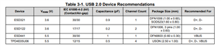
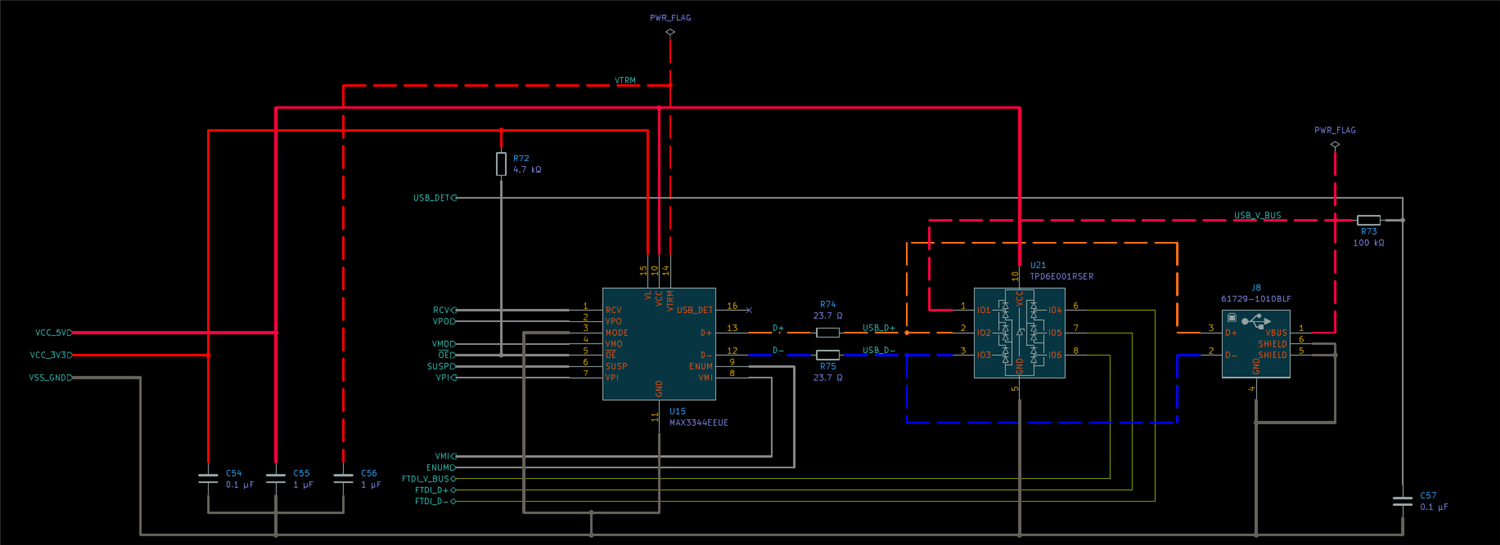
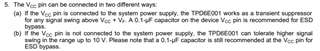
I would like to know the opinion of your support for the choice of the most suitable transient suppressor for the MAX3344 transceiver. Since my USB device, which uses the MAX3344, and complies with the USB 2.0 standard and is Full-Speed, a high-capacitance (35 pF) suppressor such as the SN65220, SN65240 and SN75240 should be assigned to it. However, I am also using the FTDI FT4232HL, which also complies with the USB 2.0 standard, but is a High-Speed device. For this device a lower capacitance (1.5 pF) suppressor is needed, such as the TPD6E001RSER. Therefore I would like to know: Would it be feasible to use the TPD6E001RSER for both devices or would this mean that the Full-Speed device would lose too much protection?

  • Hi Juan,

    There would be no issues using TPD6E001 for both interfaces, in fact I wouldn't rceommend any of the SN prefix devices you mentioned.

    These devices were released over 20 years ago and don't have IEC ESD ratings. 

    I recommend taking a look at our USB and Surge Protection App Note which will have specific device recommendations by USB type (2.0, 3.1,.. etc). 

    Here's a snippet from the app note with recommendations for USB 2.0. All these devices will provide better protection with higher IEC ESD ratings and lower clamping voltages. 

    Regards,

    Sebastian 

  • Thank you for your reply.

    In my application, the VBUS signal is not used as a power supply, but as monitoring purposes, that is, I connect it to the RESET signal of the FTDI and the USB_FUNC.VBUS to monitor when it has been connected or disconnected. Therefore, would it be necessary to connect a transient suppressor to this signal? And if so, then a transient suppressor would need to be connected to all 6 signals:(2 VBUS, 2 D+ and 2 D-). Would it be feasible to use the TPD6E001RSER for both devices

  • Hi Juan,

    If the connector is exposed to the outside world there is always a risk of ESD entering through the connector.

    Depending on the application this may or may not be frequent, but the reset pin of that IC could be exposed to ESD voltages in the kV range that could cause damage.

    If you want to protect the reset pin from ESD strikes I would recommend adding an ESD diode on the VBUS line as close to the connector as possible. You can use TPD6E001 or any ESD diode with a working voltage at or above the reset pin operating voltage. 

    Regards,

    Sebastian  

  • Thank you for your reply.

    Regards,

    Juan

  • The TPD6E001 has a vcc signal that has to be fed at 5V because I am going to work with 5V signals. The problem is that I have two different USB drivers, one from the ftdi and one from my MCU. To power the TPD6E001 I can't interconnect both VBUS signals coming from different USB connectors (one for each controller) to the VCC signal, there can only be one. Since my device has its own power supply, I think the right thing to do is to use this 5v signal to power the TPD6E001. Is this correct?

  • This is the schematic of what has been said above

  • Hi Juan,

    Yes I would recommend tying the 5V supply rail to the Vcc pin of the TPD6E001 otherwise the functionality of the device will change slightly. Mainly the breakdown voltage of each input will increase. 

    You can also use an ESD diode without a Vcc pin such as the ones I recommended earlier to protect the data/power lines you need. 

    Regards,

    Sebastian 

  • I think you misunderstood my question. I have two different USB drivers, one from the FTDI and one from my MCU. To power the TPD6E001, I can't interconnect both VBUS signals coming from different USB connectors (one for each controller: FTDI and MCU) to the VCC signal, there can only be one. Since my device has its own power supply, I think the right thing to do is to use this 5v signal to power the TPD6E001. Is there a problem if I do this?

  • Hi Juan, 

    I will be taking this thread over for Sebastian. To make sure I am understanding your application, your device has its own power supply and it is feeding into each USB connector or one power supply that goes through one connector than the next one? 

    Best,

    McKenzie

  • My USB DEVICE has its own power supply, which has a DC/DC converter that converts 24V to 5V, and another DC/DC converter that converts 24V to 3.3V.

    I have two different USB drivers, one from the FTDI and one from my MCU. I will use one transient suppressor (TPD6E001) for both drivers USB. To power the TPD6E001, I can't interconnect both VBUS signals coming from the two different USB connectors (one for each controller: FTDI and MCU) to the VCC signal of the TPD6E001, there can only be one. Since my device has its own power supply, I think the right thing to do is to use this 5v signal to power the TPD6E001. What I want to know is: if this is correct or if doing that reduces the quality of the suppression.?

  • Hi Juan, 

    It should be okay to use the 5V signal to power the TPD6E001. There should be no reduction in the quality of ESD protection. 

    Best,

    McKenzie