Part Number: DS89C21
Tool/software:
Hello,
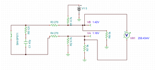
I would like to implement an AC termination for a reduced consumption with an inverted polarization to ensure a low output in case of failure of the input in high impedance or short circuit according to the following schematics.
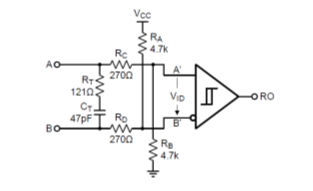
Could you please confirm the polarization circuit will have the correct behaviour (low output in case of an input HI or in short circuit) with the receiver input impedance of the DS89C21 ? and that it won't interfere with the operational mode of communication knowing that it's a low speed control application (30KHz max) , in point to point with a distance of 50cm to 1m maximum.
Thanks in advance for your help, I have no mean to simulate it (only IBIS model is available).
Best regards
Pierre