This thread has been locked.

If you have a related question, please click the "Ask a related question" button in the top right corner. The newly created question will be automatically linked to this question.

DP83826I: DP83826I: Sporadically receiving truncated packages, no error indicated in PHY

Part Number: DP83826I
Other Parts Discussed in Thread: USB-2-MDIO

Tool/software:

Hello,

We are using the DP83826I with a Soft-MAC in an Spartan-7 FPGA and experience sporadic packet receive errors. Occasionally, the MAC receives only the first part of a 551 byte packet. The previous and subsequent packet are received in full. We only see errors in the receive direction and only when we are simultaneously transmitting traffic (192 byte packets every 3ms). If we stop transmissions, all packets are received in full.

The RX traffic comes from an embedded switch on a separate board via a board2board connection.
We believe this traffic is good (see details below), but the PHY does not report any errors, low link quality or the like when it forwards a truncated packet to the MAC (which then obviously raises a CRC error).

Is there a good explanation we have overlooked that can explain this behaviour in the PHY?


More details:
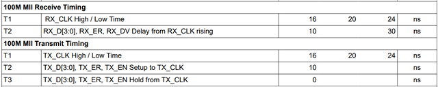
The PHY is MII Master and we use fixed-link 100Mbit full-duplex.
On the MDI side, there is a board2board connection to a main board with an embedded Marvel Switch (mv88e6290).
                                                            
┌────────────────┐                   ┌────────────────────┐
│ CPU <-> Switch │ <- Board2Board -> │ PHY <-> FPGA w/MAC │
└────────────────┘     connector     └────────────────────┘

Our understanding is that the RX_DV signal shows the period when the data is valid on the 25Mhz MII interface, and from examining the length of this signal being asserted, we see that the PHY sends too short a packet to the MAC. The number of bytes sent when the error occurs is not constant (we have seen anything from 120-something bytes to 500-something).

We have been examining the PHY status registers and found no sign of errors being reported by the PHY:
    - Good link Quality, even when error occurs: MSE_Val (reg 0218h): less than 0030h (48).
    - No Receive Errors (RX_ER line never asserted, RECR = 0, ReceiveErrorLatch in PHYSTS is 0)
    - No change in Link Quality, Status etc. (MISR1=0)
    - No Remote Fault, Descrambler Lock is active, Signal Detected, No False Carrier occurred (PHYSTS = 0605)

The fact that the error only happens when also transmitting had us thinking that we may have a noise/crosstalk problem, but then we would expect to see some full packets received with bit errors (reported as CRC errors in the MAC). We have not seen that, only short packets in the RX direction.

Also, if there was an error on receiving the symbols on the MDI side of the PHY, we would expect to see link errors or receive errors. Neither of those are seen either.

As we cannot easily analyze the signals on the Board2Board connection directly, we use a small debug interface board, which we can connect instead of the FPGA board and allows us to run the data to software on a PC, thereby simulating the FPGA functionality:
                                                                              
 ┌────────────────┐                   ┌─────────────────┐             ┌────────────────┐
 │ CPU <-> Switch │ <- Board2Board -> │ Interface Board │ <- Cat5e -> │ PC w/ FPGA sim │
 └────────────────┘     connector     │     w/RJ-45     │             └────────────────┘
                                      └─────────────────┘                     
We do not see any errors when using this setup (FPGA sim also simulates the TX traffic), so we believe the data sent by the embedded switch on the CPU board is ok.


On a side note:
Curiously, we see RX FIFO Overflow (RCSR = 0x41) being asserted when no ethernet traffic is flowing through the PHY. When we enable traffic (regardless of the direction being RX or TX), the overflow status is de-asserted after a short while. The Overflow assertion does not seem to be linked to the receive errors we see, but we are not sure what to make of this assertion, since our PHY is MII Master.
What would make the PHY assert the RX FIFO overflow when in Master mode?


Best regards,
Mikael

  • Hi Mikael,

    Please allow me until Wednesday to review and share feedback here.

    Thank you,

    Evan

  • Hi Mikael,

    Sorry for the delay here. I am still reviewing this query with the team for feedback ASAP.

    Thank you,

    Evan

  • Hi Evan,

    Thanks for the update, I'm very pleased to hear you are still looking in to this :-)

    I can add that we have been measuring the signals on the Board2Board connector and they look fine, so it does not seem like a general signal integrity problem.

    Thanks for your help looking into this,

    Mikael

  • Hi Mikael,

    This issue seems independent from PHY-side behavior, but there are some tests we check to confirm:

    1) Increasing the data IPG, if possible. 0x456[3] = '1' will set the PHY to expect 200ns IPG. Do you see similar error rate while transmitting and receiving?

    2) Using PHY's PRBS generator to simulate traffic to the FPGA, rather than CPU. This can be enabled with 0x16[13:12] = '11'. While the PHY is generating PRBS traffic, do you see a similar error?

    Cause for RX FIFO overflow is unclear in this case, but I do agree it seems unrelated to the issue.

    Can you confirm the FPGA is not transmitting any data to the PHY while this interrupt flags? It's possible there is a PPM offset between PHY/FPGA clocks, or data on the MII lines in idle state.

    Thank you,

    Evan

  • Hi Evan,

    1) We considered IPG previously, but did not pursue it further as there are 50ms between packages coming from CPU and 3ms between packages in the TX directions (to CPU), so plenty of gap between packages. Therefore we do not expect the IPG to be any issue, but please let us know if we concluded wrongly, and I will investigate how we can tune the IPG on the Marvel switch.

    2) I tried to turn off all traffic from CPU and traffic generated by FPGA, so only PRBS was enabled - by setting 0x16 to value 0x3100, but now the FPGA does not register any received traffic, and I also do not see any activity on RX_DV line, which I would have expected. When reading BISCR after enabling PRBS, I get 0x3300, so Packet Generator Status = enabled, so it is indeed running. When reading the datasheet, it is not entirely clear to me in which direction the PRBS sends the generated traffic, ie. if i need to enable loopback somewhere to get traffic into the FPGA/MAC. Clearly, I'm missing something else I need to configure.

    Regarding FIFO overflow, I can confirm that when the overflow is asserted, the FPGA is _not_ sending any traffic to the PHY. If I start traffic (in either direction), the overflow flag is de-asserted after a short while. As long as there is traffic in any of the directions, the overflow flag is de-asserted.

    Both the PHY and FPGA are connected to the same master clock (with only a clock divider involved), so we don't expect any "PPM offset" there.

    Thanks,
    Mikael

  • Hi Mikael,

    Thanks for confirming these tests - I agree IPG should not be an issue here. If FPGA expects standard ethernet frame, PRBS may not be a viable test here.

    Instead, we can try testing with FPGA transmitting to the PHY, and PHY loopback enabled.

    Please send data from FPGA, and loop back through the PHY's MAC-side with:

    0x0[14] = '1'

    0x16[2] = '1'

    My intent is to further isolate the issue by removing the CPU as a variable. As there are no errors on the PHY side during simultaneous TX/RX, my assumption is there is an issue with how the FPGA's engine is processing the MAC data during transmit.

    Thank you,

    Evan

  • Hi Evan,

    With MII + Digital loopback enabled (00h=6100, 16h=0004) and the FPGA sending 1200 byte packages every 3ms
    we still see the MAC errors, so I think we can rule out the CPU side.
    (Note: this is the same TX payload I mistakenly reported as being only 192 bytes long earlier.)

    When looking at RX_DV, I see the looped back version of the packets the FPGA has sent (RX_DV asserted for ~99.36us. every 3ms), but interestingly, in the time between packets from FPGA, I see RX_DV asserted repeatedly for 5.76us, equivalent to 64byte packets. I guess this is an artifact of the loopback mechanism, as I do not see this with real traffic when loopback is disabled. In the normal case RX_DV is only asserted for the received traffic.

    When the FPGA reports MAC_ERR, RX_DV was asserted a shorter time than expected also in the loopback mode, but with the 64byte "filler" packets in the data stream, I can now see that RX_DV stays deasserted for approx. 70 us. after the truncated packet, before the "filler" packages start appearing again. It is like the PHY stopped sending in the middle of a packet and is recovering for some time, before data starts flowing again. See screenshots:

    When loopback is enabled, the MAC error is usually asserted on the 64byte "filler" packets, but I assume this is just due to the high ratio of those compared to the "real" packets from the FPGA. This is supported by the fact that the error rate goes up in loopback mode (I saw up to 10s between errors with real traffic, only up to ~2s with loopback enabled).

    My current view is that we have ruled out the CPU side, since we still get errors in loopback mode.
    We have not see any receive errors on the CPU at any time, so I also believe MAC transmission are ok.
    Since the RX_DV de-asserts too quickly for the packet size transmitted, I also think we can rule out the FPGA MAC reception. The phy simply puts too few bytes out on the MII interface.
    So, to me our observations look like the PHY is stalling mid-packet and then recovers automatically after a short while.

    What do you make of these observations?

    Thank you,
    Mikael

  • Hi Mikael,

    Thank you for sharing the detailed observations.

    Due to lack of RX errors, signal quality issues, or fault interrupts in the PHY, this issue appears isolated to how the FPGA handles data during simultaneous TX/RX.

    There are a couple additional checks we can do to confirm this:

    1) Hardware check - please share schematic so I may review MAC connections (can email to e-mayhew@ti.com for private share)

    2) MAC timing requirements check - if possible, please probe MAC-side clock/data during simultaneous TX/RX vs. only RX case, and confirm any difference in setup/hold time seen:

    If both of these checks pass, the issue is very likely with the FPGA.

    Thank you,

    Evan

  • Hi Evan,

    Ad 1) I've sent you the schematic on email.
    Ad 2) We checked the MII timing on both RX_CLK/RX_D[0] and TX_CLK/TX_D[0], and all are the within the constraints both with TX traffic generated by FPGA and with Digital loopback enabled. They look identical.
    To dig a little more into why TX traffic leads to error in RX direction, we also examined the TX timing in the time leading up to (RX) MAC_ERR was asserted. They were also within spec. and looked as expected, so it does not look to us like the MAC is not adhering to the timing requirements. Also, as mentioned we never saw any errors reported on the CPU side for the TX traffic received from FPGA.
    We included some signal plots in the private email, just in case you notice something we missed.  

    3) Just for clarification: When the PHY is setup as Master on MII interface, I assume that the PHY is driving the RX_DV pin (as signal to MAC when it should sample data on the RX_D lines). So, if RX_DV is asserted for too short a period, how can this be a MAC issue?

    Thanks,
    Mikael

  • Hi Mikael,

    Thank you for sharing the schematic.

    The connections look good. I would like to confirm the PHY configuration as well, can a register dump be shared during the failing case?

    Is it possible to test using back to back FPGAs, only transmitting from one FPGA at a time? In this case, do you see the same error, with abnormal RX_DV?

    Also for my understanding, what do receive errors look like from FPGA side?

    Thank you,

    Evan

  • Hi Evan,

    I used a USB-2-MDIO script to dump all registers both before and after error occurred (attached). RX+TX traffic was enabled (no loopback) and script was started after the error had occurred a few times. As the readout takes quite a while to complete, the state may change while script was running, just as more errors were observed in this period.

    Unfortunately, I cannot stop the TX traffic from FPGA on the RX error condition, so I cannot force a situation where no data is sent in any direction following an MAC error. The best I can do is to stop sending RX packets from CPU when the RX error has occurred. Register dump in this scenario looked the same as the "after error" dump from above, but once I mysteriously saw PHYSTS[14] (MDI/MDIX Mode Status bit) had changed state to 0, but MDI Crossover Change Interrupt register in MISR2 was not asserted. I have run the scenario a good handful of times and not been able to reproduce the MDI/MDIX Mode status change, so I don't know how much attention to give to that.


    Regarding connecting two FPGA boards back-to-back, unfortunately we cannot do this. Firstly because we need the CPU to send the FPGA image via serial and then configure it, which is done via network. Secondly, we only have a transformer on the CPU board, not the FPGA board.


    The description I have of the error signal from the FPGA is "Ethernet MAC Rx valid & last & user". I assume this corresponds with the signals rx_axis_mac_tvalid, rx_axis_mac_tlast and rx_axis_mac_tuser, as described for the AMD TEMAC we use here: docs.amd.com/.../Normal-Frame-Reception and docs.amd.com/.../Frame-Reception-with-Errors.
    The last link contains a lengthy list of error conditions for the tuser signal, including FCS errors and packets shorter than 64 bytes, both of which I think we experience, based on the measured length of the assertion of the RX_DV signal.

    I know I keep coming back to the RX_DV assertion time, but I'm still lacking a good explanation for this, not least why traffic in TX direction can impact the RX side. If this only occurred when MII loopback was enabled, I would agree that short frames potentially could be a result of the MAC not sending the full packet, but since we also see the same without loopback, I don't think this is the issue.
    I really hope you can shed some light on this to help us understand how this can happen?

    Thanks,
    Mikael

    DP83826_RegisterDump_mdio2usb_script.txt file is open...
    Register 0000 is: 2100
    Register 0001 is: 784D
    Register 0002 is: 2000
    Register 0003 is: A111
    Register 0004 is: 0181
    Register 0005 is: 0000
    Register 0006 is: 0004
    Register 0007 is: 2001
    Register 0008 is: 0000
    Register 0009 is: 0020
    Register 000A is: 0102
    Register 000B is: 0009
    Register 000D is: 401F
    Register 000E is: 0000
    Register 000F is: 0000
    Register 0010 is: 4605
    Register 0011 is: 010B
    Register 0012 is: 0000
    Register 0013 is: 0000
    Register 0014 is: 0000
    Register 0015 is: 0000
    Register 0016 is: 0100
    Register 0017 is: 0049
    Register 0018 is: 0400
    Register 0019 is: 8401
    Register 001A is: 0000
    Register 001B is: 007D
    Register 001C is: 05EE
    Register 001E is: 0102
    Register 001F is: 0000
    Register 0025 is: 0041
    Register 0027 is: 0000
    Register 002A is: 7998
    Register 0117 is: 8147
    Register 0131 is: 2284
    Register 0170 is: 0C12
    Register 0171 is: C850
    Register 0173 is: 0D04
    Register 0175 is: 1004
    Register 0176 is: 0005
    Register 0177 is: 1E00
    Register 0178 is: 0002
    Register 0180 is: 0000
    Register 0181 is: 0000
    Register 0182 is: 0000
    Register 0183 is: 0000
    Register 0184 is: 0000
    Register 0185 is: 0000
    Register 0186 is: 0000
    Register 0187 is: 0000
    Register 0188 is: 0000
    Register 0189 is: 0000
    Register 018A is: 0000
    Register 0218 is: 002A
    Register 0302 is: 0000
    Register 0303 is: 0008
    Register 0304 is: 0008
    Register 0305 is: 000E
    Register 0306 is: 000E
    Register 0308 is: 0980
    Register 030B is: 3C00
    Register 030C is: 0410
    Register 030E is: 8400
    Register 0404 is: 0080
    Register 040D is: 0008
    Register 0456 is: 0008
    Register 0460 is: 0565
    Register 0461 is: 0010
    Register 0467 is: 0082
    Register 0468 is: 0186
    Register 0469 is: 0000
    Register 04A0 is: 1000
    Register 04A1 is: 0000
    Register 04A2 is: 0000
    Register 04A3 is: 0000
    Register 04A4 is: 0000
    Register 04A5 is: 0000
    Register 04A6 is: 0000
    Register 04A7 is: 0000
    End of file.


    DP83826_RegisterDump_mdio2usb_script.txt file is open...
    Register 0000 is: 2100
    Register 0001 is: 784D
    Register 0002 is: 2000
    Register 0003 is: A111
    Register 0004 is: 0181
    Register 0005 is: 0000
    Register 0006 is: 0004
    Register 0007 is: 2001
    Register 0008 is: 0000
    Register 0009 is: 0020
    Register 000A is: 0102
    Register 000B is: 0009
    Register 000D is: 401F
    Register 000E is: 0000
    Register 000F is: 0000
    Register 0010 is: 4605
    Register 0011 is: 010B
    Register 0012 is: 0000
    Register 0013 is: 0000
    Register 0014 is: 0000
    Register 0015 is: 0000
    Register 0016 is: 0100
    Register 0017 is: 0049
    Register 0018 is: 0400
    Register 0019 is: 8401
    Register 001A is: 0000
    Register 001B is: 007D
    Register 001C is: 05EE
    Register 001E is: 0102
    Register 001F is: 0000
    Register 0025 is: 0041
    Register 0027 is: 0000
    Register 002A is: 7998
    Register 0117 is: 8147
    Register 0131 is: 2284
    Register 0170 is: 0C12
    Register 0171 is: C850
    Register 0173 is: 0D04
    Register 0175 is: 1004
    Register 0176 is: 0005
    Register 0177 is: 1E00
    Register 0178 is: 0002
    Register 0180 is: 0000
    Register 0181 is: 0000
    Register 0182 is: 0000
    Register 0183 is: 0000
    Register 0184 is: 0000
    Register 0185 is: 0000
    Register 0186 is: 0000
    Register 0187 is: 0000
    Register 0188 is: 0000
    Register 0189 is: 0000
    Register 018A is: 0000
    Register 0218 is: 0028
    Register 0302 is: 0000
    Register 0303 is: 0008
    Register 0304 is: 0008
    Register 0305 is: 000E
    Register 0306 is: 000E
    Register 0308 is: 0980
    Register 030B is: 3C00
    Register 030C is: 0410
    Register 030E is: 8400
    Register 0404 is: 0080
    Register 040D is: 0008
    Register 0456 is: 0008
    Register 0460 is: 0565
    Register 0461 is: 0010
    Register 0467 is: 0082
    Register 0468 is: 0186
    Register 0469 is: 0000
    Register 04A0 is: 1000
    Register 04A1 is: 0000
    Register 04A2 is: 0000
    Register 04A3 is: 0000
    Register 04A4 is: 0000
    Register 04A5 is: 0000
    Register 04A6 is: 0000
    Register 04A7 is: 0000
    End of file.


  • Hi Mikael,

    Thank you again for sharing the detailed logs.

    I share your confusion with the RX_DV anomaly, we can run through a couple tests to understand the exact conditions for this to occur:

    1)  Writing 0x19[15] = '0' to disable auto-MDIX (addressing the strange MDI crossover interrupt occurring)

    2) If possible, transmitting in one direction from FPGA -> CPU, and sniffing the received packets through Wireshark or on scope 

    Aside from MDI crossover bit, I don't see any anomalies in register log to help isolate the issue. I will share with team to try to find other clues here.

    Thank you,

    Evan

  • Hi Evan,

    Good news, we finally found the root cause: Duplex mismatch.
    Even though we strapped the PHY to run 100baseT/Full duplex without auto-negotiation, the CPU side was still configured with auto-negotiation enabled.
    What we missed was that this resulted in the CPU side reporting its link partner only supporting 100baseT/Half and therefore running half-duplex. Effectively we had a duplex mismatch.

    To test, we can now either enable auto-negotiation on the PHY OR disable auto-neg. on both ends and force 100baseT/Full on the CPU side. Either configuration makes our error disappear.

    From my understanding, what happens in duplex-mismatch mode is that the CPU side (running half-duplex) occasionally detects a collision when it tries to send a packet to the FPGA at the same time as receiving a packet.
    The CPU side will then send a jam signal and stop it's current transmission (thus "truncating" the outgoing packet, which is what we see as a short asserted RX_DV signal). The PHY side ignores the jam signal, because the Full duplex configuration disables collision detection, so no error is reported.

    The only thing that surprises me a little is that I would expect the CPU side to also discard the UDP packet received from FPGA, which triggered the collision, but I did not see any missing packets in the FPGA->CPU direction.

    Anyway, issue is resolved and it now makes sense how enabling/disabling TX data from FPGA can impact the RX side.

    Thanks for all your help,
    Mikael