This thread has been locked.

If you have a related question, please click the "Ask a related question" button in the top right corner. The newly created question will be automatically linked to this question.

TCAN1463-Q1: TCAN1463-Q1 silent mode not working

Part Number: TCAN1463-Q1

Tool/software:

Currently we are using TCAN1463DRQ1 CAN transceiver IC and STM32H5 nucleo board for evaluating TCAN1463DRQ1 CAN transceiver IC.

There are 4 operating modes for TCAN1463DRQ1 as mentioned in data sheet.

– Normal mode

– Silent mode

– Standby mode

– Low-power sleep mode

We are using PEAK CAN USB adaptor and PCAN view for monitoring CAN frames with proper CAN termination.


Please find below other pin configuration for your reference.


PIN3 - VCC - connected to +5V.

PIN5 - VIO - connected to +3.3V.

PIN7 - INH - Keep floating. Not connected.

PIN9 - WAKE - connected to +10V.

PIN10 - Vsup - connected to +10V.

PIN11 - INH_MASK - connected to ground through capacitor.


we are able to establish and verify CAN communication in Normal mode, but we are facing following issues when we try to test the silent mode.

  • We set the TCAN1463DRQ1 mode as a silent mode by setting standby and enable pin (please refer below image for your reference),but STM32H5 evaluation board doesn’t receive any CAN frame which we are sending from PCAN view. And PCAN view shows bus heavy message status as soon as we send CAN message from PCAN view to STM32H5 eval board. We expect that in this condition nFault pin should go to logic low, but it still remains in logic high state.

  • Rohan,

    Can you please share some waveforms of the CAN bus when trying to send from the PCAN to the STM32H5. And what is the state of INH when this testing is going on, as well as EN and nSTB?

    Regards,

    Eric Hackett 

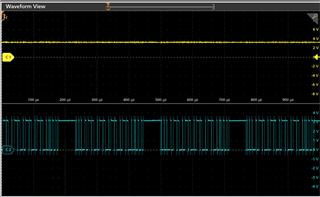
  • Hello Eric....Please find attached screenshot of the CAN signal which are getting transmitted from the PCAN to the STM32H5 EVAL board for your reference (on C2 channel).
    Please find below the in detail pin state of EN,nSTB and INH pins.

    EN pin - WRITE_PORT_PIN(CAN_TRANSRCVR_EN_PORT, CAN_TRANSRCVR_EN_PIN, GPIO_PIN_RESET);
    nSTB pin - WRITE_PORT_PIN(CAN_TRANSRCVR_NSTB_PORT, CAN_TRANSRCVR_NSTB_PIN, GPIO_PIN_SET);
    INH pin - not connected (floating)
    INH_MASK pin- low to high transition
    WRITE_PORT_PIN(GPIOF,INH_MASK_Pin,GPIO_PIN_RESET);
    HAL_Delay(5U);
    WRITE_PORT_PIN(GPIOF,INH_MASK_Pin,GPIO_PIN_SET);

  • Hi Rohan,

    Is there any change you can probe at INH, EN, and nSTB?

    And for C2 above, was that RXD output of TCAN1463-Q1, or you are probing at somewhere else?

    Regards,

    Sean

  • Do we need to consider INH_MASK and INH pin to actiavte silent mode for the TCAN1463-Q1.
    Also please find below the psudo code for each mode. Please review the psudo code for each mode and let me know the modification, if required.

    psudo code to put TCAN1463-Q1 into normal mode =
    SET EN pin
    SET nSTB pin

    psudo code to put TCAN1463-Q1 into silent mode =
    RESET EN pin
    SET nSTB pin

    psudo code to put TCAN1463-Q1 into standby mode =
    RESET EN pin
    RESET nSTB pin

    or 

    SET EN pin
    RESET nSTB pin

    psudo code to put TCAN1463-Q1 into go to sleep mode =
    SET EN pin
    RESET nSTB pin

    psudo code to put TCAN1463-Q1 into sleep mode =
    SET EN pin
    RESET nSTB pin

  • Rohan,

    INH_MASK is only used to activate/deactivate INH function in silent mode, since it's pulled to GND this pin will not be used. We asked for INH state because we want to see if the device was in sleep mode.

    From the waveform above, what are C1 and C2? (Which pin are you probing at?)

    Please capture RXD, INH, nSTB, EN signals using an oscilloscope.

    Regards,

    Sean

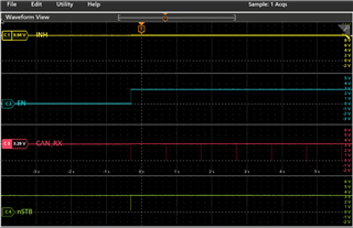
  • 1. Please find below the attached image and information for normal mode.
    In our schematic we have connected 10V to VSUP pin, hence we can observe 10V on INH pin. Refer C1 channel waveform (yellow color) from attached image.
    To enter into Normal mode we need to set EN and nSTB pins high. Refer C2 (blue color) and C4 (green color) channel waveforms from attached image.
    After making both EN and nSTB pins high we are able to transmit and receive CAN message from PCAN PC Utility. Refer C3 channel waveform (red color) from attached image.

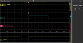
    2.Please find below the attached image and information for silent mode.
    In our schematic we have connected 10V to VSUP pin, hence we can observe 10V on INH pin. Refer C1 channel waveform (yellow color) from attached image.
    To enter into Silent mode first we need to put CAN transceiver into normal mode and then we can switch to silent mode. In the below attached image we can observe that we set the EN and nSTB pins high to put transceiver into Normal mode. Refer C2(blue color) and C4 (green color) channel waveforms from 0 ms to 5ms timestamp.
    After this we are putting  transceiver into silent mode by resetting EN pin and setting nSTB pin.  Refer C2(blue color) and C4 (green color)channel waveforms from 5ms time.


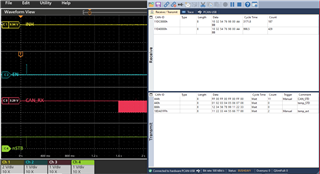
    3.Please find below the attached image and information for silent mode issue.
    we can observe INH on 10V (Refer C1 channel waveform in yellow color). Also we first put CAN tranceiver into normal mode and then we can switch to silent mode(Refer C2 waveform in blue color and C4 waveform in green color at 0s timestamp)
    After putting CAN tranceiver into silent mode we tried to send CAN messages from PCAN view PC utility to our device. As soon as we hit the send button on PCAN view utility,
    PCAN view bus status goes into BUS HEAVY state and  its continuously send the CAN message. Refer C3 waveform in red color from 1.6s and device do not receive any CAN message from PCAN View PC utility.