This thread has been locked.

If you have a related question, please click the "Ask a related question" button in the top right corner. The newly created question will be automatically linked to this question.

TIOS102: quiescent supply current

Part Number: TIOS102

Tool/software:

Hi team,

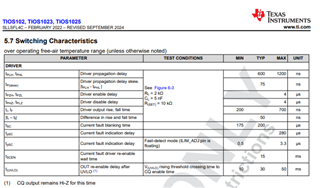
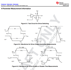
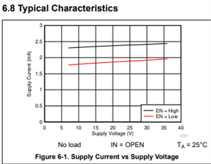
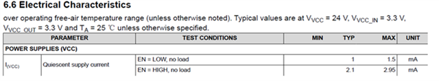
My customer plan to use TIOS102 (without LDO). I want to know if the IVCC below refers to the current consumption of 24V? Is it because of the internal LDO that causes the maximum static current of about 2.95mA?

What is the power supply current of the logic level input?

Thanks

Lillian

  • Hi Lillian,

    All versions of the TIOS102 are completely supplied from the 24V supply voltage.  Both with and without LDO versions of this device have an internal LDO to create the voltage needed for the digital core. 

    The "with LDO" versions (TIOS1023 and TIOS1025) can supply additional current to an external circuit and the digital IO voltage is fixed to either 3.3V or 5V depending on the part number.

    The "without LDO" version cannot supply current to an external circuit and requires that a low voltage reference voltage be supplied for the digital IO level shifters allowing this device to be used in either 3.3V or 5V applications where an external regulator is present.

    The quiescent supply current therefore covers all current consumed by the device including the internal LDO, digital core, and any leakage paths that may be enabled based on the IO pin and driver state.

    Regards,

    Jonathan

  • Hi Jonathan,

    Thanks for reply.

    I have another question. According to 8.4.3 and Table 8.7 of the Datasheet, when configuring the Push-pull mode, is the following understanding correct? If it is correct, how should the time of this toggle cycle be set?

    ※EN is set to H, GPIO controls IN

    Thanks

    Lillian 

  • Hi Lillian,

    I don't know what version of the datasheet you are referring to, but the most recently released version does not have a table 8.7 or a section 8.4.3.

    From your drawing, it looks like you are wanting the MCU_GPIO to be of a "return-to-zero" (RZ) type instead of a "non-return-to-zero" (NRZ) type of pulse.  The TIOS102x devices are simply and expect a NRZ format and the OUT pin will follow the IN pin. 

    Therefore the propagation delays and rise/fall times are the only timing requirements that need to be considered and those are specified in the switching characteristics table in the datasheet.

    Regards,

    Jonathan

  • Hi Jonathan,

    Got it.

    Our product is planned to be used in 4 units per machine. According to the following maximum value calculation, the static power consumption can reach 4*2.95*24=283mW, and the heat generation is quite serious.

    So I want to confirm again, when the "without LDO" version is connected to an external 3.3V, does it only provide a reference voltage? Does it have the function of powering the internal logic? In other words, after using external power supply, will the static current decrease?

    Thanks

    Lillian 

  • Hi Lillian,

    The TIOS102 is completely powered from the 24V VCC supply. 

    The VCC_IN is the reference voltage for the digital IO pins and is not used as a supply for the digital core.  This is why there are not separate line item specifications for the with and without LDO devices.

    The TIOS1023 and TIOS1025 differ with the TIOS102 in that the digital IO levels are fixed at either 3.3V or 5V depending on the part number, and the internal LDO can be used to provide up to 20mA of additional current to an external circuit.

    However, the power for the digital core is stepped down from the 24V supply in all versions of the TIOS102x device.

    Regards,

    Jonathan

  • Hi Jonathan,

    Understood, but now 4*2.95*24=283mW

    According to the power consumption requirements of the whole machine, the current static total power consumption theoretically calculated has exceeded 1/3. Do we have any way to make some improvements?
    Thanks
    Lillian
  • Hi Lillian,

    There are no adjustments to the device and the datasheet max conditions cover the full operating condition range for Process, Voltage, and Temperature. 

    The datasheet "max" is equal to 2.95mA.  However, reducing the operating voltage and temperature results in a lower current level which is more realistic for a normal application.  At 24V and at 25C, the current is approximately 2.4mA which saves you about 50mW (4*2.4*24=230.4mW).

    Regards,

    Jonathan