This thread has been locked.

If you have a related question, please click the "Ask a related question" button in the top right corner. The newly created question will be automatically linked to this question.

TPS54140: it does n't work in low temperature of -33 degrees and 24v input.

Part Number: TPS54140

Tool/software:

Thank you for allowing me to contact you in this way.

I use TPS54140. I configured the circuit as follows.
 
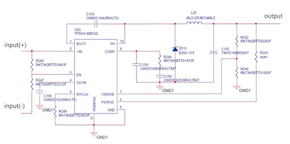
The input power is supplied from 24V to 34V and the output voltage is 5.7V.
 
It operates normally in all input power ranges at room temperature.
 
Currently, 5 out of 44 have the following phenomenon.
 
When 28V is supplied at a low temperature of -33 degrees, it outputs 5.7V normally.
 
However, when 24V is input at a low temperature of -33 degrees, it outputs 0V.
 
When 24V is input at room temperature again, it operates normally.
 
The recommended minimum temperature on the data sheet is -40 degrees.
 
The recommended input voltage is also 3.5V or higher.
 
I have the following questions.
 
1) What do you think could be the cause of this problem?
 
2) Is there anything I can improve in the circuit?
 
3) Can this phenomenon occur if the backside soldering of the component is incorrect?
 
If you have any questions, please contact me by email.
 
I know you are busy, but I would appreciate a quick response.
Thank you. Have a nice day.
  • Hello,

    Can you confirm all of the component values for the schematic?

    Looking up the part numbers provided, the inductor appears to be 330uF. That is too large of an inductance for this type of design. 

    Are you planning to use this device in a very light load? If so, you should design for an inductor at the full load capability of the buck converter, then operate at the light load.

    Here is an example Webench design similar to your stated operating conditions: https://webench.ti.com/appinfo/webench/scripts/SDP.cgi?ID=C22117FA1A55732F

    The compensation may also be tuned in the wrong way which may be what is making it unstable at cold temperature. Changing your inductor will affect the compensation. Use Webench or the design calculator to help with compensation calculations: https://www.ti.com/tool/download/SLVC432

    All of the component pads must be soldered properly. If the device is not soldered to the PCB properly, it may not function properly or at all.

    Best regards,

    Ridge

  • Thank you for your answer.

    It is difficult to show the entire circuit diagram for security reasons.

    However, when 24V voltage is applied, the load current flows 30mA.

    Thank you for your advice on the design.

    Actually, I conducted the following test.

    I did a low-temperature test by replacing only the TPS54140 parts that I have on the same board.

    I replaced the TPS54140 5 times.

    However, only 1 out of 5 does not work at 24V.

    The remaining 4 work fine at 22V.

    So I actually suspect the problem is with the parts rather than the circuit design.

    I wonder what you think.

    If you can answer, please let me know.

    Best regards.

  • Hello,

    The inductor value is far too large for this application if it is in fact 330uH given the part number shared in the schematic. This means that the compensation is likely not tuned properly as well, leaving the design vulnerable to more conditions where it becomes unstable even if some of your devices appear to operate as expected. 

    I recommend adjusting the design to be in-line with the Webench and calculator recommendations then test again.

    Best regards,

    Ridge

  • Hello,

    Closing this thread due to inactivity.

    Best regards,

    Ridge