This thread has been locked.

If you have a related question, please click the "Ask a related question" button in the top right corner. The newly created question will be automatically linked to this question.

DS125BR401: How to load data from external EEPROM in Master Mode?

Part Number: DS125BR401

Tool/software:

dears,

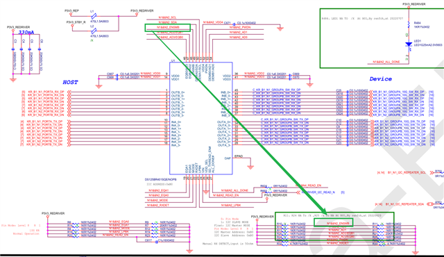
My customer used SMBus Master Mode (ENSMB = float) to load register data from external EEPROM (AT24C02C; EEPROM address is 0xA0, 3 repeater AD[3:0] is 0XB0)to DS125BR401,

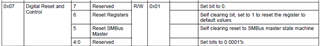
, but it failed to load data from EEPROM when power up; however, if reset the registers by setting the bit 6 (Reset Registers) of 0X07 register (Digital Reset and Control), the data may be loaded from the external EEPROM.

i noticed that there is a pin, READ_EN, it is said in the datasheet,: " When using an External EEPROM, a transition of READ_EN pin from high to low starts LVCMOS the load from the external EEPROM", is it also necessary for the Master Mode? the datasheet does not require READ_EN pin high-to-Low transition in master mode work sequence (9.5.2 SMBUS Master Mode). 

when does DS125BR401 load the data from external EEPROM? will the power quality affect the data loading?

the customer set the mode at 10G-KR, they also noticed that the 2 bits, 0x26[6:5] (MODE_DET Status), may change between 11 and 00, is it abnormal? As the datasheet says these 2 bit "Only functions when MODE Pin = Automatic", could we just ignore them? 

please help to have a look of the issues.

thanks a lot!

  • Hi Andrew,

    In SMBus master mode, the EEPROM load starts when the READ_EN pin is pulled low. An external EEPROM is only used in SMBus master mode, so any information in the datasheet related to an EEPROM applies in SMBus master mode.

    How many redrivers will load their configuration from a single EEPROM?

    • If only one redriver, you can simply tie the READ_EN pin to GND and EEPROM load will begin on power up.
    • If multiple redrivers, you will need to tie READ_EN of the first device to GND, tie ALL_DONE of the first device to READ_EN of the second device, tie ALL_DONE of the second device to READ_EN of the third device, etc. This is necessary to prevent multiple redrivers from trying to read the EEPROM at the same time.

    You can ignore MODE_DET STATUS since these bits only function when the MODE pin = Automatic.

    Best,

    Lucas

  • dear Lucas,

    there is only 1 DS125BR401 and the customer already pulled READ_EN  to GND. it is strange that the external EEPROM data not to be loaded at power up, but could be loaded after  reset the registers by setting the bit 6 (Reset Registers) of 0X07 register (Digital Reset and Control). would you please help to check if any action of RESET may enable EEPROM to be loaded?

    I am also have have question about the function of READ_EN,  it is said " When using an External EEPROM, a transition of READ_EN pin from high to low starts LVCMOS the load from the external EEPROM", but as READ_EN is pulled to GND, will the redriver pull it high during power-up? when it pull READ_EN  to High? The customer did not notice HIGH level of READ_EN, so how could there be transition from HIGH to low?

    thanks a lot!

  • dear Lucas,

    in addition, what is the work flow of DS125BR401 to load the EEPROM data? will it keep loading the data after  READ_EN pin being pulled LOW until success or will stop loading after a certain time?

    thanks! 

  • Hi Andrew,

    Thank you for your clarifications.

    Can you clarify, does EEPROM load successfully after writing 0x07[6]=1 to reset register values? Or are you writing 0x07[5]=1 to reset the SMBus master state machine?

    The pin description for READ_EN is a bit misleading. EEPROM load will begin when READ_EN is pulled low, so tying READ_EN to GND will initiate EEPROM load on device power up.

    DS125BR401 will attempt to load data from the EEPROM several times. After a fixed number of tries, I believe the redriver will stop attempting to load data. On a similar device, EEPROM load will be declared a failure after 64 attempts. I'm unclear if the number of attempts for DS125BR401 is different.

    I have a few a debug questions.

    1. Can you probe the ALL_DONE pin and report the voltage level both at power up and after register reset is performed?
    2. Can you share the schematic for me to review?

    Best,

    Lucas

  • dear Lucas,

    the schematics is as below:

    as double checked with the customer, they reset the SMBus master by sending 00100001(0x21)  to 0X07, not reset the whole registers.

    all_done pin voltage is not easy to check as their system is  immerse in water. but the EEPROM Read done bit is 0 when failed to load and turn to 1 when succeed to load.

     compared to their old project, where DS125BR401 may load EEPROM data without resetting SMBus master, there are 2 difference in this issued project:

    1. the number of DS125BR401 changed to 1 from 2 (the schematics shows the connection of ENMSB & read_EN is correct)

    2. the BMC device is not the same (there is also BMC device connected on the same SMBus of DS125BR401), is it the reason that cause the SMBus error when loading EEPROM upon power up? is there any difference of the Behavior of the SMBus state machine when RESET compared to power-up? 

    DS125BR401 use SMBus rather than I2C Bus, I notice that customer might use it as I2C, so might it cause any confliction of comunication in some case?

    Please help to share your valuable advice. the customer is in urgency now.

    Thanks a lot! 

  • Hi Andrew,

    Thank you for sharing the schematic, I reviewed device U1. Did you try to share a second image? If you did, I am unable to see it. Can you share a schematic for the second redriver?

    I have a few questions based on the schematic.

    • Can you try depopulating C617? I'm wondering if this capacitor is preventing the redriver from properly recognizing low input on the READ_EN pin.
    • I see ALL_DONE is connected to the READ_EN pin of a second redriver. Can you confirm, do 2 redrivers share the same I2C bus? Will they both load their configuration from the same EEPROM?
    • Is there any pull-down resistor on the READ_EN pin of the second redriver?
    • Can you confirm SDA and SCL lines include pull-up resistors?

    Thank you for the confirmation on which register bit is used to reset the SMBus master. This matches my understanding of how to restart EEPROM load.

    You mention that the board is immersed in water. I have a few questions about this.

    • Are components directly in contact with water? Water is a conductor and can damage components that are not specifically rated for underwater usage, including DS125BR401.
    • Can the customer test with a system that has not been immersed in water before? I'd like to see if the issue still occurs without water immersion.

    Regarding the BMC device: Is this device maintaining master control of the I2C bus? DS125BR401 needs to assume master control when it loads its configuration from the EEPROM. It will revert to an I2C slave after the load is complete.

    SMBus is built on I2C and is therefore generally compatible with I2C devices. It is common that our customers connect the SMBus interface of our redrivers and retimers to other I2C devices. I think it is very unlikely there is some compatibility issue between I2C and SMBus.

    If you're interested, you can review the following app note for more info about I2C/SMBus compatibility: sloa132_smbus_compatibility_with_i2c.pdf

    Finally, can you share the name of the customer for my information?

    Best,

    Lucas

  • dear Lucas,

    the issue is confirmed to be caused by the I2C confliction with other circuit, the customer fix it now.

    thanks a lot!