Other Parts Discussed in Thread: ALP
Tool/software:
Hi,
We are trying to get the evm board to work on a NVIDIA Xavier NX devkit board, but so far we have not been able to get i2c to get detected. First we are trying something simple, just getting the 0x3D device to get listed in the i2c bus of the Jetson, but we are failing to get it. We connected it using j9 on the EVM and the 40pin header on the Jetson
We have it like:
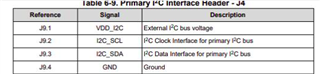
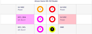
j9.1 -> pin1
j9.2 -> pin5
j9.3 -> pin3
j9.4 -> pin6
The jumpers on the board are all default, and we are plugging in power to both devices, we have a ub953 with a cam connected via the fraka adapter which is getting power, and using i2cdetect -y -r in all the available busses to try and check for 0x3D to show up. but have not been able to get it. Is there something we are missing?
We are not using the mini-USB cable nor the TI software, is it mandatory?
Regards,
Andres