Because of the Thanksgiving holiday in the U.S., TI E2E™ design support forum responses may be delayed from November 25 through December 2. Thank you for your patience.

This thread has been locked.

If you have a related question, please click the "Ask a related question" button in the top right corner. The newly created question will be automatically linked to this question.

DS250DF230: Why does the output rise when the retimer is powered up, even though there is no input signal?

Part Number: DS250DF230

Tool/software:

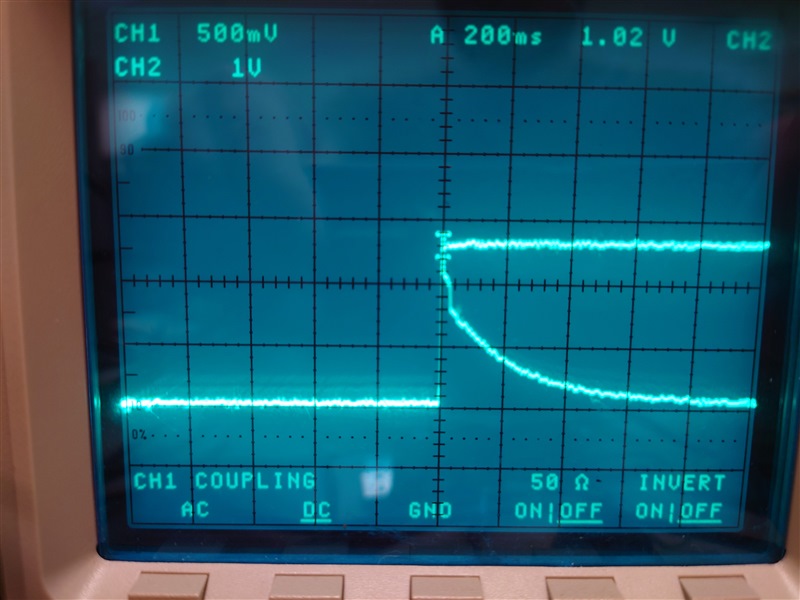
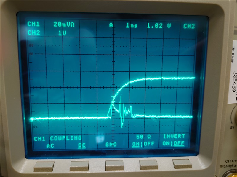
When power is applied to the Retimer, the waveforms of the Retimer's power supply (ch1) and 100nF-decoupled output signal(ch2) look like the attached file.
At this time, no input signal is applied to the Retimer and the output is open.
Please tell me why the Retimer output rises.
  • Hi Takashi-san,

    I believe this is due to DC bias getting applied to DS250DF230 output when power is applied.

    Thanks,

    Drew

  • Hi Drew-san,

    Dose the output driver have CML scheme? 

    How much is the output impedance of the driver expected while writing the registers for initial setup?


    Given the output driver has CML scheme and output impedance of 100Ohm diff., 

    We assume that the 100nF-decoupled output signal on 100Ohm diff. termination would be several hundreds mV.

    But, We saw approximately 0V on it.

    Thanks,

    Takashi

  • Hi Takashi-san,

    Can you clarify some details on your measurement?  Are you measuring single-ended or differential?  Are you measuring 0V immediately after power up, or after some time?

    I'd have to double check the output impedance of the driver.  The driver is typically muted while the retimer does not have CDR lock.

    Thanks,

    Drew

  • Hi Drew-san,

    I measured the 100nF-decoupled output signal single-ended immediately after powering up and it measured 0V.

    Thanks,

    Takashi

  • Hi Takashi-san,

    Drew is out of office today and can provide additional feedback later this week.

    I see in the datasheet electrical characteristics section that the typical differential output amplitude with TX disabled is 6.1mVppd. Your measurement of 0V single-ended immediately after power up seems to match this specification.

    Best,

    Lucas

  • Hi Takashi-san,

    I observed similar behavior as your initial scope shot if the scope is configured with high impedance termination.

    If the scope channel is configured with 50 Ohm termination, the signal from the DS50DF230 on power up is much smaller.

    High impedance termination:

    50 Ohm termination:


    Do you have any open questions or concerns at this point?

    Thanks,

    Drew