DP83826E: ESD test issue at 8kV in the air

Part Number: DP83826E

Tool/software:

Hi, I am looking for support to address ESD issue on the Ethernet PHY DP83826E. This happen when the board is supply by PoE and an ESD discharged arrived by an other connector referenced to the ground of the board. The PoE signals are referenced to the PoE ground which is himself separated from the main ground of the board.

The pins 17, 29 & 30 are short circuited when a 8kV is applied on the other connector. The ESD gun is referenced to an earth reference that is the same as the PoE supply. 

Do you have any idea about what is happening and what could be the solution to support the ESD discharge ? 

  • Hi Sebastien,

    Please share the schematic and pictures of the test setup.

    What is the passing ESD range?

    What class performance is required?

    Thank you,

    Evan

  • Hi Evan,

    What do you mean by passing ESD range ? We want to pass at 8kV in the air, and it seems we succeded at 6kV. But with higher voltage the Ethernet PHY is destroyed.

    Not sure about the class performance, but we must answer the IEC 61000-4-2 as follow:

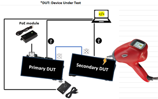
    Picture of the test set up: 

    The ESD gun is referenced at the same earth reference as the PoE Module.

    When we discharge in the Secondary DUT at higher than 6kV, we destroy the ethernet PHY of the Primary DUT. 

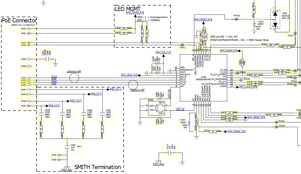
    About the electronic schematic of the Primary DUT it is not clear what to share because we don't totally understand what is happening.

    Also the project is confidentiel so I can't share the full document. Can we plan a meeting to discuss if needed ? 

    We think that the discharge is going through the CAN bus between DUTs, and after to the Ethernet Phy (through the pin 17) of the Primary because it has some signals connected to the Ethernet connector (pin 29 & 30). But we are not totally confident about the analysis. 

    For information, if we do the test only with the Primary DUT (no Secondary DUT connected, no cable), we don't have the issue and we pass the ESD test.

    Thanks for your help,

    Sebastien

  • Hi Sabastien,

    When you mention the PHY is destroy, Could you be more specific on this behavior?

    • Are you no longer seeing the PHY power up properly?
    • Are you able to see any link up at all after performing ESD test?
    • May I ask what is the power consumption under normal stage and damage stage

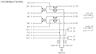
    Based on the schematic, I did not see any isolation network. Is all the network inside the PoE connector. If so, could we have more information on the PoE connection on how does the isolation network connected?

    --

    Thank you,

    Hillman Lin

  • Hi Hillman Lin,

    We can observe when following the ESD impulsion, a short-circuit have been detected on the board. We desoldered the PHY and investigate the component. The following pins became short-circuited to GND : pin 17, pin 30 and pin 29.

    After soldering a new PHY in place of the previous component everything came back alive.

    The isolation network is in the Ethernet connector: https://abracon.com/Magnetics/ARJM11.pdf

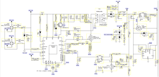
    And about the PoE connection I can add this part of the schematic:

    Thanks for your help,

    Sebastien

  • Hi Sebastien,

    Please expect some delay in feedback as Hillman is OoO.

    Thank you,

    Evan