This thread has been locked.

If you have a related question, please click the "Ask a related question" button in the top right corner. The newly created question will be automatically linked to this question.

TIOL1123: TIOL1123 VCCOUT doesnt work

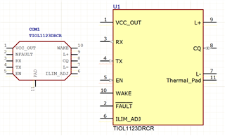
Part Number: TIOL1123
Other Parts Discussed in Thread: ISO6763, TIOL112

Tool/software:

Hi,

I need a help to TIOL1123 circuits

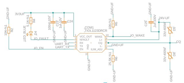
TIOL1123 Vout doesn't work

VCCOUT Pin = 0V

I don't understand where I'm making the mistake.

We built 2 boards and I didnt try replacing. 2 boards the same result on VccOut. When I check all of the pins on boards, there is only one diffrence on pins, One of them CQ=19V and another one CQ=0V. 

When I checked for short circuit, there is no fault. 

Shouldn't VCCOut output 3V3 even if there is no load? Does the signal need to be given from any pin? 

We are currently only checking the power outputs on the boards. We haven't moved on to the communication checks yet. That's why we are giving 0V to all input pins of TIOL1123 ( RX,TX,Wake, En,IoFault). Does this affect VccOut? 

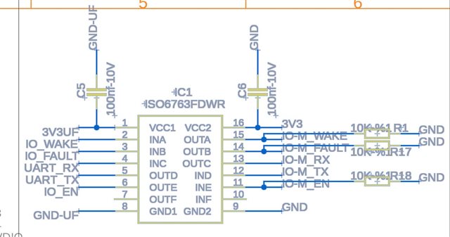
We feed the ISO6763 integrated circuit that we use for isolation from VCC OUT and we control all inputs and outputs of TIOL1123 with ISO6763. Is this causing a problem? 

I am waiting for your valuable opinions and suggestions, I wish you good work. 

Sincerely.

  • Hi Halid,

    As you can see from the Device State Diagram in the datasheet, the LDO should always be on as long as there is a supply voltage provided between L+ and L- and is in the range 7V to 36V.  This LDO is used to supply the internal digital core and can provide up to 20mA of current to an external load.  It is internally limited to 35mA to protect against initial start-up inrush current due to large decoupling capacitors and accidental short circuit conditions.

    Since these are new boards, please verify the devices have been assembled in the correct orientation with pin1 of the device soldered to the pin 1 pad of the board.  While it is an unlikely scenario, it is possible the devices were assembled in the wrong orientation.

    Also, because there is a non-LDO version of this device (TIOL112), please make sure the device markings have a "3" included on the package.  If the "3" is missing and the TIOL112 device has been assembled, the VCC_OUT pin is instead a VCC_IN and the device is expecting a 3V3 supply voltage to be provided from an external source.  Again this is unlikely, but something to verify.

    That's why we are giving 0V to all input pins of TIOL1123 ( RX,TX,Wake, En,IoFault). Does this affect VccOut? 

    Only TX and EN pins are Inputs.  Do not try to supply RX, WAKE, and NFAULT with 0V because these are Output pins.  If they are trying to drive High, and you have directly connected them to 0V, then this could create a high current fault condition and cause the device to shut down.

    Can you provide a complete listing of all the voltage levels for each individual pins?

    Can you provide a board layout for review?

    Is it possible to test the TIOL1123 device pin voltages by itself without the ISO6763 device connected?

    Regards,

    Jonathan

  • Hi Jonathan,

    Thank you for support me.

    I checked IC orientation and Pin 1 position is correct.

    I checked IC marker and I saw 1123 gravur on IC.

    Pins voltages:

    L+ = +23.49V

    CQ = 0.12V

    L- = 0V

    Wake = 0.05V

    Ilim_Adj = 0.01V

    VccOUT = 0V

    EN = 0.07V

    Tx = 0.02V

    Rx = 0.04V

    IO_Fault = 0.01V

    Board prewiev is attached.

    Tomorrow I will remove the 663 integrated circuit and try again.

    Best Regards.

    Halid

  • Hi Halid,

    Thanks for the additional information.  I haven't seen anything that is the obvious issue, so I am curious to see if removing the ISO chip makes any difference and is somehow causing an issue such as an over current condition.

    I think I see vias in the GND-UF copper that connects the Thermal Pad and most of the passive components which I assume make an internal connection through some plane to the GND-UF copper connected to pin 7.  Can you just confirm these are connected on the board?  I can't see a connection from the image, and I'm wondering if there is a missing connection even though they have the same net name which could prevent proper operation.

    Regards,

    Jonathan

  • Hi Jonathan,

    I removed the ISO IC and ran the tests again. But there was no change. When I measured the pin voltages, all pins except L+ and IO_Fault pins show 0V.

    L+ = 22.8V
    IO_Fault = 0.4V

    If TIOL1123 falls into overcurrent, the IC, VccOUT = 0 occurs ?

    I changed the TIOL1123 IC and the results still did not change.

    Pin 7 GND UF connection is present. There is no missing connection.

    Regards.

    Halid

  • Hi Halid,

    If TIOL1123 falls into overcurrent, the IC, VccOUT = 0 occurs ?

    Yes, if the current load on VCC_OUT exceeds the 30mA limit, the LDO is disabled.  I just verified this on an EVM (Link) by applying a variable current load to the VCC_OUT pin.  Once the current load exceed 30mA, the VCC_OUT voltage dropped from 3.3V to 0V.

    The full schematics can be found in the EVM User's Guide, but the schematics are very similar and I do not see anything that looks problematic.

    I'm not sure what to suggest at the moment besides trying to isolate the device as best as possible and try to methodically debug every trace and component.  If possible ohm out a blank board looking for possible shorts, bad components, or components such as resistors that may have the wrong value (i.e 10 ohms instead of 10k, etc.)

    I don't know if you have the ability to get small wires soldered directly to the L+, L-, and VCC_OUT pads of a TIOL1123 device by itself, could verify if the IC is even functional or has been damaged in any way.  However, since you have tried with multiple devices, I would expect there is some issue with the PCB.

    Regards,

    Jonathan

  • TIOL1123DRCR_v1.rar

    Hi Jonathan,

    I disconnected all the connections on the back of the device and re-energized the L+ and L- pins. When I energized, I observed electrical arcs in the connection cables. I suspect that the arc is caused by the pin gaps or the proximity of the thermal pad to the pins. I am sending you the TIOL1123 library I use. I would be glad if you could check it and get back to me.

    (I check the power and signal layer short circuits every time, but there is no power loss from the power supply or other components on the same board, and I do not receive a short circuit warning.)

    Best Regards.

    Halid

  • Hi Halid,

    If I was able to import your library into Altium and do a side-by-side comparison on your footprint and TI's recommended footprint.  The thermal pads appears to be the same length and width and match the recommended footprint in the datasheet.  However, the pin pads on your footprint are a little larger than TI's recommended footprint. 

    The copper clearance between the pin pad and the thermal pad in your footprint is about 0.18mm, and it is about 0.275mm in TI's footprint.  This is a difference of 0.095mm.  I don't know if this is enough to get arching, but I'm also perplexed by how you are seeing an arch on the cable if the idea is it would be arching under the device. 

    The pin names and numbers appear correct.

    I would expect the arch to occur at the location where the clearance is the smallest.  So if the arching is in the cable, then the issue might not be related to the footprint clearance.  I'm also a bit perplexed that you don't have any shorts that would create a sustained current load when the board is energized. 

    The TIOL1123's LDO should automatically re-enable when the current load drops below the 30mA limit, so even a momentary arching coming from something like a capacitor that had residual charge, shouldn't permanently disable the device.

    Have you tried any lower voltages?  The TIOL1123 has a min voltage of 7V, so you might try lower voltage levels to see if there is any difference.

    You have verified the package has the correct markings for the 3.3V LDO version.  Can you send a picture of the device and markings so I can check the lot code information? 

    This is also unlikely, but for debug I might suggest you try to connect an external 3V3 supply to VCC_OUT and see if that allows the rest of the device to function.  This would confirm that there isn't a non-LDO TIOL112 device in this package, or an issue with the internal bond wire for this pin. 

    Regards,

    Jonathan