This thread has been locked.

If you have a related question, please click the "Ask a related question" button in the top right corner. The newly created question will be automatically linked to this question.

TLK2501: Receiver Mask Requirement

Part Number: TLK2501

Tool/software:

Hello,

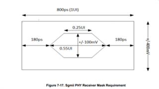
I measured an eye width of about 310 ps on the TLK2501 serial receiver pins (see attached file). However the eye has a poor signal quality, really slow rising time.

My questions:

1. The receiver side is specified to have differential jitter tolerance of 0.6UI. Should the attached eye be fine regarding the signal quality?

2. Please give me the serial receiver mask requirement for TLK2501, so it's easier for me to check whether my measurement results according to specification or not.

Thanks in advance.

Regards,

Theresia

  • Hi Theresia,

    The serial receiver mask requirements of TLK2501 are the following:

    • VID greater than 200mV. This means eye height greater than 400mV.
    • Jitter less than 0.6UI. This means eye width greater than 0.4UI.

    From your eye diagram, the data rate appears to be 2.5Gbps. Can you confirm if this is correct?

    The measured eye height is 639.8mV which meets the mask requirement. The measured eye width is 310.4ps. Assuming 2.5Gbps transmission, this is equivalent to 0.776UI which meets the mask requirement.

    Since the serial receiver mask requirements are met, the TLK2501 will likely receive this signal without issues. However I cannot say this with full confidence due to the unusual shape of the eye diagram.

    Best,

    Lucas

  • Hi Lucas,

    thanks for replying.

    Yes, the data rate of the eye is 2.5Gbps.

    I do face the same dilemma as you due to the shape of the eye. TI has mask requirement for the ethernet phy (see attachment). I was asking something similar, so i can integrate it to our oscilloscope. 

    1) Do you have similar mask document for TLK2501? It is important where the 0.4UI minimum eye width located (time axis)

    2) Can you please measure and show me how the eye looks like at the serial receiver side of the TLK2501? I get the unusual shape of the eye no matter what configuration before the receiver pins. It is always degraded.

    Regards,

    Theresia

  • Hi Theresia,

    Lucas is out of office today.  He will follow up with you on this early next week.

    Thanks,

    Drew

  • Hi Theresia,

    Unfortunately I'm not aware of any eye mask file created for TLK2501. This is a legacy device which was released nearly 25 years ago and I have limited support resources.

    The eye you are measuring at the TLK2501 serial receiver pins is a result of your transmitter settings and channel characteristics. The receiver cannot have any effect on the signal before it enters the device.

    1. What settings are configured on your transmitter?
    2. Do you have a measure of s-parameters or insertion loss for your transmission channel?

    It may be possible that some equalization can help improve the shape of the signal before it reaches the TLK2501. This also may not be necessary since the signal does meet the receiver mask requirements.

    Best,

    Lucas

  • Hi Lucas,

    I measured a "less degraded eye" on the TI Eval-board, if I external loopback the TLK2501 transmitter to its receiver. 

    1. for the transmitter setting please see the attached picture. To save time I only show it in single ended. 

     The transmitter is an ANY to CML translator IC. Can you suggest a ANY/CML to CML with equalization IC to replace the transmitter as depicted in the picture?

    2. no, i don't have these measurements. The differential lines on the board are adjusted to 100 Ohm impedance by the PCB fabricator. Other differential signals on the board with the same datarate have no signal quality problem. 

    If TI doesn't have any translator IC with equalization, I would go with your assessment about the signal meeting the receiver mask requirement.

    Regards,

    Theresia

  • Hi Theresia,

    I reviewed your attached diagram and have the following comments regarding receiver hardware configuration.

    • I see you are using 100nF AC coupling capacitors. The datasheet recommends using 1nF-10nF capacitors. Using a larger AC coupling value results in a lower cutoff frequency, meaning less low frequency noise will be blocked by the capacitor.
    • I see you are using a 100nF decoupling capacitor on V_term. The datasheet does not recommend placing any decoupling capacitors on V_term.

    TI does have a wide portfolio of CML equalizers. I can share some part recommendations, but I first want to check if you've observed any issues with your current system design? Although the input eye diagram is a bit abnormal, it does meet the TLK2501 eye mask requirements so design changes may not be necessary if there are no issues observed.

    Best,

    Lucas