This thread has been locked.

If you have a related question, please click the "Ask a related question" button in the top right corner. The newly created question will be automatically linked to this question.

TUSB522P: Board Configuration

Part Number: TUSB522P

Tool/software:

I am looking at the datasheet for the TUSB522P and see that the OS, EN_RXD, EQ and DE pads are connected to 47kOhm resistors and ground and 3.3 voltage in the Embedded Host Application. I believe that the only pins that are connected to the USB connector are the high speed signals, Voltage and Ground, but I was wondering if anything needs to be connected to the OS, EN_RXD, EQ and DE pads. Do they need to be connected to an outside voltage source?

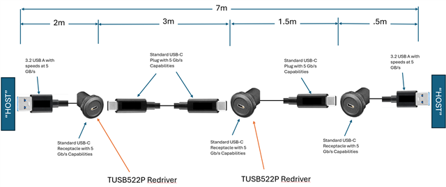
Also, I noticed that RX2N/P has either no capacitor or a 330 nF capacitor. However, I have a "Host" on either side of my assembly and was wondering if that would mean that the 100nF capacitors should be on all Tx/Rx lines? I have included an image of my simplified assembly.

Best, Arron

  • Hi Arron,

    You should connect the OS, DE, and EQ pins to pullup and pulldown resistors as shown in the datasheet application section. These are configurable settings on our device that can be tuned to get the best signal quality through your board. Additionally, EN_RXD should be pulled up to VCC with a 4.7K resistor.

    I have a "Host" on either side of my assembly and was wondering if that would mean that the 100nF capacitors should be on all Tx/Rx lines?

    The capacitor value is not related to the host vs device side of the USB connection, it is a requirement for all USB transmitters (TX) to be AC coupled with 100nF or 220nF with the option to include 330nF AC coupling capacitors on receivers (RX). If you have an embedded host or device application, you should use one 100nF capacitor on the RX between the host and the TUSB522P because this is the only capacitor on the line (essentially the same as AC coupling the host transmitter).

    In the diagram you show there is no embedded host, so you can follow the standard 100nF on transmitters with optional 330nF on receivers.

    Best,

    Shane

  • Hello Shane,

    Would it be possible to connect the pull up and pull down resistors to the same VBUS and GND on the USB connector? And you mention the optional 330nF on receivers, does this mean if there is no "embedded host" all capacitors are optional on the receivers end? And what are the benefits of the 330 nF capacitors on the receivers? 

    Best,

    Arron

  • Hi Arron,

    You cannot directly pull up the EQ/DE... inputs to the VBUS because the voltage will be too high. The USB VBUS will be 5V while our CMOS inputs cannot go above 4V. You should step the voltage down to 3.3V first, similarly to our TUSB522P EVM.

    You can use the GND from the connector to pull down the input pins.

    if there is no "embedded host" all capacitors are optional on the receivers end?

    Yes, the USB spec does not have a requirement for capacitors on the receiver end. The benefits of having a capacitor is that it can help protect the port against ESD strikes and removing unwanted DC bias from the RX line. You can see more details in this ECN issued by the USB-IF: 8037.USB 3.1 ECN Rx AC Coupling Capacitor Option(1).pdf

    Best,

    Shane