This thread has been locked.

If you have a related question, please click the "Ask a related question" button in the top right corner. The newly created question will be automatically linked to this question.

DS90UB947-Q1EVM: About the EQ status

Part Number: DS90UB947-Q1EVM
Other Parts Discussed in Thread: ALP, USB2ANY

Tool/software:

Hi Teams,

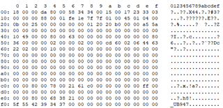
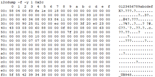
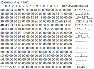
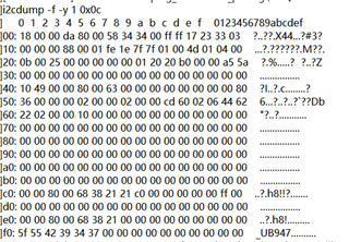
We bulided a new solution with 947/948, sometimes the screen display would shaking, we dump the 947/948 registers map.

And we compared them with correct module, we found the NG module's 948 register 0x3B = 0x00, the OK module is 0x3F,

so what's the meaning of 0x3B(EQ status)

  • Good afternoon,

    The 0x3B register EQ status read from 0x3B is the EQ level set by the adaptive EQ to compensate for the attenuation.


    1. Between the good and NG 947-948 systems, what other differences are there in register values? Could you please provide the full register dumps?

    2. For the NG system with shaking screen, could you please probe the LOCK pin on the DES?

    3. Are there back channel CRC errors read on the SER?

    Best regards,
    Ikram

  • Hi Ikram,

    These are the dump maps of 947 and 948, we sorry but did not probe the Lock pin of Des

    Best Regards.

  • Hi Yao,

    Thank you for sending these in. It looks like there are a few CRC errors on SER reg 0xA- 0xB, this could indicate SI issues. 

    1. Can you please probe LOCK pin on DES and check if it drops when flickering occurs

    2. Read SER 0xA - 0xB repeatedly, maybe every few seconds, and check whether it increases continuously.

    3. If possible, use the BIST sequence as described in 948 datasheet.


    And just for some background on you system:

    - Are both SER and DES on custom boards?
    - How many units tested and how many show this issue?
    - For the NG boards, how frequently is issue occurring?

    Best regards,
    Ikram

  • Hi Ikram,

    1. Can you please probe LOCK pin on DES and check if it drops when flickering occurs

    --->>>It is still high level(lock);

    2. Read SER 0xA - 0xB repeatedly, maybe every few seconds, and check whether it increases continuously.

    --->>>This Time, it is 0xff (see the below pic),

    3. If possible, use the BIST sequence as described in 948 datasheet.

    --->>>The 948 did not bulid on our main unit.


    And just for some background on you system:

    - Are both SER and DES on custom boards?

    --->>>No
    - How many units tested and how many show this issue?

    --->>>We had already got 3 board;
    - For the NG boards, how frequently is issue occurring?

    --->>>The one/two boards: Only 1 time

              The third board: almost  0.2~0.5%.


    Can you explain the CRC registers of 947:

    1:The more CRC errors report, connection failure increase, is it correct?

    2:If one 947 report more CRC errors everytime startup, wether this 947 was broken?

    3:When the shaking happen, we can fixed it by reset 947 and the Display panel(which 948 bulid in)

    Best regrads.

  • Hi Yao,

    1. The back channel CRC errors count indicates signal integrity issues. So this could be related to IL/RL not matching channel specification through the layout, parts selections, connector, cable, etc. 

    2. Are all the necessary errata being applied for the 947? Could you please share the script?

    3.  Was LOCK probed continuously? It's possible that LOCK drops only occasionally during the shaking/ flickering.

    Can you also try using 947 SER PatGen? It would help to check whether flickering occurs only with 947 LVDS input, or whether also with internal PATGEN.

    Best regards,
    Ikram

  • Hi Ikram,

    This the 947 startup script, the 948 is init by display panel.

    Now, we had found 3 pcs 947 shaking, we still could not probe LOCK pin of 947 during the shaking/ flickering.

    How we can using 947 SER PatGen?

  • Hi Yao,

    Are you able to connect ALP (FPD-Link GUI) to the 947? You could use an Aardvark to connect to the 947 I2C and use ALP from your PC to configure this.

    Otherwise, could you share the display timings so that I can write a script for you?

    BR,
    Ikram

  • Hi Ikram,

    I am very sorry, what is the ALP? How we can connect it to 947?And what is the Aardvark?

    Of cause I can share the display timing to you ,but I can not understand which display timing I should share to you.

    Best Regards.

  • Hi Yao,

    ALP is the GUI for testing FPD-Link devices. https://www.ti.com/tool/ALP
    W
    hen testing with the EVMs, you can run ALP from your computer and connect to the EVM via USB2ANY.
    Otherwise, you can also use an I2C adapter like an Aardvark to connect the PC to I2C of the FPD-Link device.


    The display timing would be for the display panel. The timings would be like this below, or the display panel datasheet might have values with min. and max. values
     

    # THW = Horizontal Total Pixels = AHW + HBP + HFP + HSW
    # TVW = Vertical Total Lines = AVW + VBP + VFP + VSW
    # AHW = Hoizontal Active Pixels
    # AVW = Vertical Active Lines
    # HBP = Horizontal Back Porch Pixels
    # VBP = Vertical Back Porch Pixels
    # HSW = Horizontal Sync Width Pixels
    # VSW = Vertical Sync Width Lines
    # HSP = Horizontal Sync Polarity: 0 = Positive, 1 = Negative
    # VSP = Vertical Sync Polarity: 0 = Positive, 1 = Negative
    # PCLK = Pixel Clock Rate in MHz

    Best regards,
    Ikram
  • Hi Ikram,

    These are the spec which got from display panel  manufacturer。

    Best Regards.

  • Hi Yao,

    Thank you for sending these, and I will work on a PATGEN script for the 947 with these timings.

    Best regards,
    Ikram

  • Hi Ikram,

    These are the startup waves of Ser and Des .

    Yellow: PDB of 948;

    Purple: Lock of 948;

    Bule: Pclk output form 948;

    Green: PDB of 947.

    So, whether the timing sequence isn't fixed, and 947's init is more early than 948?

    Best Regards.

  • Hi Yao,

    Can you please check whether the power-up sequence follows the 947 datasheet? PDB should be high after there is stable OLDI clock input.

    Also, your PCLK rate (according to the display timings you shared) is 47.98 MHz.


    For 947, that rate (below 50 MHz) is only supported by Single-Link mode using only DOUT0. Could you change the MODE_SEL settings and cable connection so that it's in single-link mode?

    Best regards,
    Ikram

  • Hi Ikram,

    Thank you very much, we had almost fixed this issue,but we still have one issue need you help:

    The display panel had been bulit before our Head Unit, and display panel had made a rule which 948 init by itself, 947 init by head unit.

    If display panel init 948 follow below steps:

    1:display panel write 948 register A;

    2:display panel write 948 register B;

    3:display panel write 948 register C;

    4:display panel write 948 register D;

    Case A:If head unit write 948 register F between step2 and step3, whether this action would broken the 948's initialization?

    Case B:If head unit write 948 register F at the same time with step3, whether this action would broken the 948's initialization?

    Best Regards.

  • Hi Yao,

    Could you please tell us what steps or changes you made to fix this issue? It would help to make sure that the link bandwidth specifications are met as we shared in the last response.

    The initialization steps for the 948 have to follow the datasheet sequence. Could you explain what you mean by these register write steps? I'm not sure what you were describing. Otherwise, it would help if you shared the script and marked which steps you are asking about here.

    Best regards,
    Ikram

  • Hi Ikram,

    1:We set the pclk to 50.5M;

    2:We mission Errata 3(below Pic), they only run one time before, now we set them retry 20 times;

    Display panel make a rule which 948 init by itself, but head unit need to write/read 0x68 and 0x69 of 948, maybe display panel are writing 948's other registers at this time.

    So we want to kown whether this action would broken the 948's initialization?

    Best Regards.

  • Thank you for sharing these. Please give me 1-2 days to verify and get back to you.

    Best regards,
    Ikram

  • Hi Yao,

    The "Timing Confirmation" code should be run after there is LOCK, and stable video data being sent through. Is it possible to change the code so that the host SoC executes this code in sequence rather than the MCU on deserializer side? Is there a way you could verify whether the display I2C activity is occurring during this?

    2:We mission Errata 3(below Pic), they only run one time before, now we set them retry 20 times;

    Also, just for testing purposes, has there been stable video or while running this full script, does it always show error after running several times as you mentioned?

    Best regards,
    Ikram