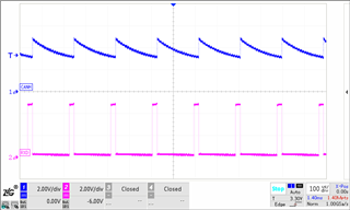
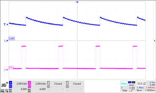
TCAN1145-Q1: The CANH/L waveform is abnormal and the register cannot be configured

Part Number: TCAN1145-Q1

Tool/software:

Hello, the TCAN1145DMTRQ1 used in our product found that it could not communicate (the circuit diagram is below), and the chip was tested, please help analyze the cause of the problem;

Test 1: The waveform of CANH and CANL is measured as follows, the waveform changes to sawtooth wave, the waveform of CANH and CANL is the same, the amplitude is basically the same, and the period is 200us (5KHZ frequency);
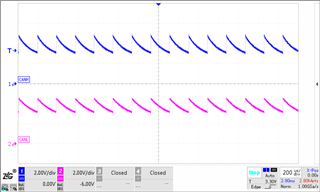
Test 2: Comparing the waveforms of CANH and TXD/RXD simultaneously, it was found that the period of the sawtooth wave was consistent with that of TXD/RXD;
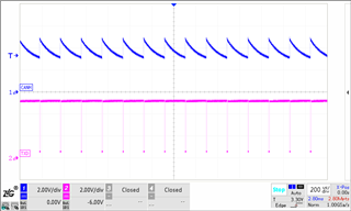
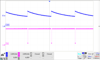
Test 3: The MCU cannot configure the mode of TCAN1145 through SPI.

Test 4: Change the TXD frequency to 500KHz through the MCU, and the test waveform result is the same as that of test 1;

Test 5: The resistance value of CANH to GND is about 11MΩ, the resistance of CANL to GND is about 11MΩ, and the resistance of CANH to CANL is about 125Ω(same as normal IC).

Test 6: After the MCU stops sending TXD packets, the CANH/L sawtooth wave disappears and becomes low.

Above, please help analyze whether it is the TCAN1145 chip damage? If the chip is damaged, please help confirm the cause of the damage? How to circumvent it?

  • Hello,

    Thanks for bringing this question to E2E, it looks like CANH and CANL voltage are not correctly biased.

    Can you check the level of VCC and VIO? And what is the INH level?

    Is there a second node on the bus? CAN needs ~60 Ohms to work correctly, if there is only one node as shown in the schematic, the termination will be 120 Ohms which is not the desired value.

    Regards,

    Sean

  • 1:VIO=VCC=4.98V

    2:INH=0V;

    3:There just one node,but the other node is also one node, and its waveform is fine;I tried to plug the problematic chip into a node, and the test waveform was still problematic, and the resistance of the CANH/CANL changed to 62;

    Above, please help with the cause of the problem;THKS!!!

  • Hi,

    INH = 0V means the device may not be powered up, would you also check the VSUP level?

    If everything is setup correctly, the chip may be damaged. The possible cause can be high voltage transients at specific pin exceeding the abs max ratings. In that case I would recommend to do a customer return for failure analysis.

    Do you have a filed application engineer or sales representative assigned to this product?

    Regards,

    Sean

  • HI

    VSUP=12V

    I will ask my FAE to fix this problem.

  • Hi,

    After power on the device will first enter standby mode and pull INH high, you measured INH = 0 after power on, right?

    Would you please capture INH, VIO, VCC and VSUP on the same plot?

    Regards,

    Sean

  • HI

    The plot as follow;

  • Hi,

    For some reason it's going to sleep mode after power on, if there's no mode change using SPI it would an abnormal phenomenon. 

    Please ask the FAE to do a customer return for our failure analysis.

    Regards,

    Sean